This post is about bugs and their solutions on embedded Linux.
Bug 1
Remove internet connectivity on Gateway device. For the first time, plug in USB device with swupdate.swu, no firmware update is performed. For the second time, plug in USB device with swupdate.swu, firmware update occurs. When internet connectivity is removed, it should not do firmware update. So it is a bug.
Solution:
Check the gateway system time against x.509 certificate validity period. If system time is outside x.509 validity period, swupdate does not run. That is because swupdate software checks the x.509 certificate. The problem has nothing to do with internet connectivity.
# openssl x509 -in x509.crt -text -nount
validity: not before
not after
# date
-- show system time
Compare the system time and x509 certificate validity
Bug 2
When using mobile App to connect to Gateway device via BLE, multiple occurrence of DBUS error message "Rejected send message" is seen in journal log. This error message should not happen.
Solution:
Using dbus-monitor, we can see the dbus system message. There is method call from Bluez to config daemon, there is a signal and method return in response to the method call. The method return is rejected by the dbus daemon and dbus error message is printed out.
The gateway sends GATT Indicate to mobile app, mobile app responds with GATT Confirm. The Indicate is used to transfer data. Confirm is the acknowledgement. When mobile app sends Confirm to gateway, Bluez receives it, it sends dbus confirm to config daemon. And the next chunk of data is sent from config daemon to Bluez. The method return is also sent out by the config daemon. The config daemon uses dbus python library. The solution is in dbus python library. We have to check the dbus must_not_reply flag. If the flag is set, we stop the library from sending out method return.
Bug 3
If Gateway is physically connected to ethernet and has a wifi, and if ethernet link is not able to up, the gateway is not able to use wifi. The gateway should be able to auto failover to wifi.
Solution
Use network manager to check the link, if the ethernet link is not up, auto switch to wifi. The network manager config file provides checking of the link status.
Bug 4
When doing high throughput network application over ethernet , the CPU is loaded to over 90%.
This slows down the response time of other processes.
Solution:
The ethernet driver was using interrupt driven mode, switching to NAPI , and implement TSO so that segmentation of the packets is handled by NIC card. This way reduces the CPU load.
Showing posts with label Embedded. Show all posts
Showing posts with label Embedded. Show all posts
Sunday, 2 February 2020

Saturday, 15 April 2017
Embedded Product Design on Linux
An embedded product on Linux involves several stages. As an example, we use a Zigbee embedded product on Linux to discuss this.
The software components that make up an embedded product:
Dynamic UI: HTML, JQuery, Javascript, XML data, CGI process
Application and Libraries: Many applications, and third-party libraries
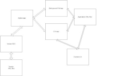
The figure above shows the interaction among the application processes, CGI app and Dynamic UI.
Linux Kernel and Drivers:
It maybe required to integrate new drivers into Linux kernel space, to enable the SoC on the main board.
Bootloader:
It maybe required to modify boot loader if we upgrade to new generation of flash and DRAM IC.
Real-Life Embedded Systems problems and solutions:
Problem:
Old carrier board is responding to Zigbee Ping command, and can find its IEEE address.
New carrier board is responding to Zigbee Ping command, but cannot find its IEEE address.
Reasons: Firmware is upgraded in New carrier board, so a upgraded SDK is required to work with the new firmware in New carrier board.
Debugging process: In Linux, open the serial port where the Zigbee module is connected, then set the firmware in carrier board to command mode, then send the Zigbee Ping command to the carrier board.
Problem:
Power-off the board immediately without proper shutdown sequence will cause linux file system corruption.
Solution: Ask MSP430 to set an interrupt to MPC8315 when the power switch is pressed. An interrupt handler is added to linux kernel (as a linux driver module) to handle MSP430 interrupt. The driver module will create a kthread to listen to the interrupt. When interrupt arrives, a user space helper function is called (by using usermode helper API).
The userspace function handles the proper shutdown sequence, such as carrying out the "init 0" command.
Problem:
We want to copy DRAM content.
Solution:
void loader(void)
{
long * ptr = loki_plus_dram;
int i;
for (i=0; ptr[i]!=0x1FFFF; i++)
{
*((long *)ptr[i]) = ptr[i+1];
}
return;
}
Problem:
Unable to communicate to TI cc2530's UART 1 port.
Solution:
In IAR Workbench, Project->Options, choose C/C++ compiler, set:
HAL_UART_DMA = 0
HAL_UART_ISR=2
This is a must for the source code to call hal_uart_isr() function in hal_uart.c
Problem:
Wifi camera lost connection to Wifi AP after 1 day, meaning Wifi AP cannot detect the Wifi camera after 1 day.
Solution:
In /etc/hostapd.conf, set wpa_strict_rekey = 0
or set wpa_group_rekey = 0 and wpa_ptk_rekey = 0 if maintaining wpa_strict_rekey = 1
Problem:
The Bluetooth program on linux is not able to read all data from Glucometer, read function hang, need to power off/on Glucometer .
Solution:
Use a function called setsockopt to set socket to non-blocking with timeout.
setsockopt(sk, SOL_SOCKET, SO_RCVTIMEO, (struct timeval *)&tv, sizeof(struct timeval));
ret = read(sk, buf, sizeof(buf));
if (ret == -1)
{
timeout!!
read again
}
Problem:
debug statements are lost if we do not have serial port to monitor them
Solution:
Define a debug macro
//DEBUG functions
#define LOG_OUTPUT stderr
#define LOG(level, ...) \
{
fprintf(LOG_OUTPUT, level); \
fprintf(LOG_OUTPUT, __VA_ARGS__); \
fflush(LOG_OUTPUT); \
}
#define DEBUG(...) LOG("Myglucohealth ", __VA_ARGS__)
Actual usage:
DEBUG("Can't find adapter %s\n", adapter);
Normally the debug statements will be sent to console, but we can redirect them to anywhere with a easy command:
<process_command> &> /mnt/storage/bluetooth/process_command.log &
---> redirect both stdout and stderr to a file
Problem:
A TCP client connected to TCP server every 60 seconds and close the connection after sending a message. After 6 hours, socket call failed, saying "socket: too many open files"
Solution:
The TCP server must close the socket that is returned by accept(). And the TCP client should close the socket first, then the TCP server close it. This is due to the TIME_WAIT settings which will create waiting burden on the TCP server if the TCP server closes the socket first, and if the TCP server is a busy one.
Tips:
Use netstat to check for open socket connections
Use "ls /proc/<pid>/fd" to check for open file descriptor
Turn off SO_LINGER, call it after open the socket, eg: setsockopt(sd, SOL_SOCKET, SO_LINGER,...);
Problem:
When there are simultaneous Wifi and Ethernet transmission to the DUT, and DUT does not receive data via the Wifi after a few hours.
Debugging:
Check the interrupt mask and interrupt enable register bits. On the general interrupt controller (GIC), the Wifi and ethernet bits are adjacent to each other. When data is received at the hardware interface, internet status bit is set. When inside the ISR, interrupt enable bit is disabled, and interrupt mask bit is masked out. When exiting ISR, interrupt enable bit is enabled, interrupt mask bit is cleared. If ISR interrupt enable bits is not set, something is amiss.
Solution:
The problem is due to a hardware error that ethernet interrupt bit will affect the Wifi interrupt bit. The software workaround is to enable the Wifi and Ethernet interrupt enable bits in the ISR when exiting ISR.
The software components that make up an embedded product:
Dynamic UI: HTML, JQuery, Javascript, XML data, CGI process
Application and Libraries: Many applications, and third-party libraries
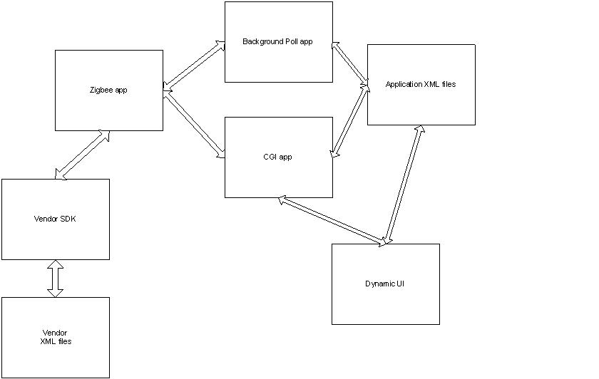
The figure above shows the interaction among the application processes, CGI app and Dynamic UI.
Linux Kernel and Drivers:
It maybe required to integrate new drivers into Linux kernel space, to enable the SoC on the main board.
Bootloader:
It maybe required to modify boot loader if we upgrade to new generation of flash and DRAM IC.
Real-Life Embedded Systems problems and solutions:
- Zigbee Carrier board integration:
Problem:
Old carrier board is responding to Zigbee Ping command, and can find its IEEE address.
New carrier board is responding to Zigbee Ping command, but cannot find its IEEE address.
Reasons: Firmware is upgraded in New carrier board, so a upgraded SDK is required to work with the new firmware in New carrier board.
Debugging process: In Linux, open the serial port where the Zigbee module is connected, then set the firmware in carrier board to command mode, then send the Zigbee Ping command to the carrier board.
- Board Graceful shutdown:
Problem:
Power-off the board immediately without proper shutdown sequence will cause linux file system corruption.
Solution: Ask MSP430 to set an interrupt to MPC8315 when the power switch is pressed. An interrupt handler is added to linux kernel (as a linux driver module) to handle MSP430 interrupt. The driver module will create a kthread to listen to the interrupt. When interrupt arrives, a user space helper function is called (by using usermode helper API).
The userspace function handles the proper shutdown sequence, such as carrying out the "init 0" command.
- Move DRAM content forward:
Problem:
We want to copy DRAM content.
Solution:
void loader(void)
{
long * ptr = loki_plus_dram;
int i;
for (i=0; ptr[i]!=0x1FFFF; i++)
{
*((long *)ptr[i]) = ptr[i+1];
}
return;
}
- TI Zigbee chipset cc2530 UART 1 setup:
Problem:
Unable to communicate to TI cc2530's UART 1 port.
Solution:
In IAR Workbench, Project->Options, choose C/C++ compiler, set:
HAL_UART_DMA = 0
HAL_UART_ISR=2
This is a must for the source code to call hal_uart_isr() function in hal_uart.c
- Wifi camera lose connectivity to Wifi AP:
Problem:
Wifi camera lost connection to Wifi AP after 1 day, meaning Wifi AP cannot detect the Wifi camera after 1 day.
Solution:
In /etc/hostapd.conf, set wpa_strict_rekey = 0
or set wpa_group_rekey = 0 and wpa_ptk_rekey = 0 if maintaining wpa_strict_rekey = 1
- Glucometer timeout issue:
Problem:
The Bluetooth program on linux is not able to read all data from Glucometer, read function hang, need to power off/on Glucometer .
Solution:
Use a function called setsockopt to set socket to non-blocking with timeout.
setsockopt(sk, SOL_SOCKET, SO_RCVTIMEO, (struct timeval *)&tv, sizeof(struct timeval));
ret = read(sk, buf, sizeof(buf));
if (ret == -1)
{
timeout!!
read again
}
- Add debug statement control:
Problem:
debug statements are lost if we do not have serial port to monitor them
Solution:
Define a debug macro
//DEBUG functions
#define LOG_OUTPUT stderr
#define LOG(level, ...) \
{
fprintf(LOG_OUTPUT, level); \
fprintf(LOG_OUTPUT, __VA_ARGS__); \
fflush(LOG_OUTPUT); \
}
#define DEBUG(...) LOG("Myglucohealth ", __VA_ARGS__)
Actual usage:
DEBUG("Can't find adapter %s\n", adapter);
Normally the debug statements will be sent to console, but we can redirect them to anywhere with a easy command:
<process_command> &> /mnt/storage/bluetooth/process_command.log &
---> redirect both stdout and stderr to a file
- TCP socket: too many open files:
Problem:
A TCP client connected to TCP server every 60 seconds and close the connection after sending a message. After 6 hours, socket call failed, saying "socket: too many open files"
Solution:
The TCP server must close the socket that is returned by accept(). And the TCP client should close the socket first, then the TCP server close it. This is due to the TIME_WAIT settings which will create waiting burden on the TCP server if the TCP server closes the socket first, and if the TCP server is a busy one.
Tips:
Use netstat to check for open socket connections
Use "ls /proc/<pid>/fd" to check for open file descriptor
Turn off SO_LINGER, call it after open the socket, eg: setsockopt(sd, SOL_SOCKET, SO_LINGER,...);
- Simultaneous Wifi and Ethernet transmission, and data lost
Problem:
When there are simultaneous Wifi and Ethernet transmission to the DUT, and DUT does not receive data via the Wifi after a few hours.
Debugging:
Check the interrupt mask and interrupt enable register bits. On the general interrupt controller (GIC), the Wifi and ethernet bits are adjacent to each other. When data is received at the hardware interface, internet status bit is set. When inside the ISR, interrupt enable bit is disabled, and interrupt mask bit is masked out. When exiting ISR, interrupt enable bit is enabled, interrupt mask bit is cleared. If ISR interrupt enable bits is not set, something is amiss.
Solution:
The problem is due to a hardware error that ethernet interrupt bit will affect the Wifi interrupt bit. The software workaround is to enable the Wifi and Ethernet interrupt enable bits in the ISR when exiting ISR.
Wednesday, 21 December 2016
Bluetooth Protocol and IEEE11073
Bluetooth Protocol Stack:

Bluetooth Stack Partitioning:

host controller - Bluetooth hardware
Bluetooth host - the PC
HCI - Host Controller Interface
Pairing:
Pairing is the process of establish the right to make a connection. Once the units have been paired and provided the paired unit is "trusted" then connecting becomes automatic. Otherwise you must respond each time an attempt is made to connect that it is ok. Keeping the unit in a connected state makes it easy and convenient to accept calls but you do pay for the higher battery drainage.
Pairing is also and act of exchanging of authentication key.
Inquiry Procedure:
The inquiry procedure enables a device to discover which devices are in range, and determine the addresses and clocks for the devices. The inquiry procedure involve a unit (the source)sending out inquiry packets (inquiry state) and then receiving the inquiry reply .The unit that receives the inquiry packets (the destination), will hopefully be in the inquiry scan state to receive the inquiry packets. The destination will then enter the inquiry response state and send an inquiry reply to the source. After the inquiry procedure has completed, a connection can be established using the paging procedure.
Paging Procedure:
With the paging procedure, an actual connection can be established. The paging procedure typically follows the inquiry procedure. Only the Bluetooth device address is required to set up a connection. Knowledge about the clock (clock estimate) will accelerate the setup procedure. A unit that establishes a connection will carry out a page procedure and will automatically be the master of the connection. The procedure occurs as follows:
1: A device (the source) pages another device (the destination ) : Page state
2: The destination receives the page : Page Scan state
3: The destination sends a reply to the source. : Slave Response state: Step 1
4: The source sends an FHS packet to the destination : Master Response state: Step 1
5: The destination sends it's second reply to the source. : Slave Response state : Step 2
6: The destination & source then switch to the source channel parameters :Master Response state: Step 2 & Slave Response state: Step 3
Bluetooth Protocol:
On Linux, I use Bluez, an open source implementation of Bluetooth protocol. Bluez will run a daemon called bluetoothd, kernel modules called rfcomm, bluetooth, bnep, etc. Bluez is used for receiving and sending the Bluetooth messages.
MCAP - Multi Channel Adaptation Protocol. It is used by HDP. It facilitates the creation of communication link for exchanging commands, and data links to transfer actual Medical Device data. MCAP guarantees reliable transmission of data.
SDP - Service Discovery Protocol. It is used by all Bluetooth profiles to discover available services on remote devices, so that connections over L2CAP can be established.
L2CAP - Logical Link Control and Adaption Protocol. It supports protocol multiplexing, packet segmentation and re-assembly, quality of service, re-transmission, flow control. It is only used for ACL link.
Bluetooth Profile:
It is an interface specification, resides on top of the Bluetooth core specification.
It specifies:
Health Device Profile - HDP. It is designed to facilitate transmission and reception of Medical Device data. It also performs SDP behavior, to connect to remote HDP devices.
IEEE 11073 stack. It performs building, transmission, reception, parsing of IEEE PDU packets for the associated IEEE 11073 agent/manager. It links to HDP.
Generic Access Profile - GAP. It describes the required features of all Bluetooth profiles, including inquiry, connection, authentication procedures.
Device ID Profile - DIP. It provides device specific information through use of the SDP. If vendor specific info is required, this profile provides specific way to acquire this info. It enables identification of the manufacturer, product id, product version. It is useful in allowing a PC to identify a connecting device and download appropriate drivers.
Bluetooth Stack Partitioning:
host controller - Bluetooth hardware
Bluetooth host - the PC
HCI - Host Controller Interface
Pairing:
Pairing is the process of establish the right to make a connection. Once the units have been paired and provided the paired unit is "trusted" then connecting becomes automatic. Otherwise you must respond each time an attempt is made to connect that it is ok. Keeping the unit in a connected state makes it easy and convenient to accept calls but you do pay for the higher battery drainage.
Pairing is also and act of exchanging of authentication key.
Inquiry Procedure:
The inquiry procedure enables a device to discover which devices are in range, and determine the addresses and clocks for the devices. The inquiry procedure involve a unit (the source)sending out inquiry packets (inquiry state) and then receiving the inquiry reply .The unit that receives the inquiry packets (the destination), will hopefully be in the inquiry scan state to receive the inquiry packets. The destination will then enter the inquiry response state and send an inquiry reply to the source. After the inquiry procedure has completed, a connection can be established using the paging procedure.
Paging Procedure:
With the paging procedure, an actual connection can be established. The paging procedure typically follows the inquiry procedure. Only the Bluetooth device address is required to set up a connection. Knowledge about the clock (clock estimate) will accelerate the setup procedure. A unit that establishes a connection will carry out a page procedure and will automatically be the master of the connection. The procedure occurs as follows:
1: A device (the source) pages another device (the destination ) : Page state
2: The destination receives the page : Page Scan state
3: The destination sends a reply to the source. : Slave Response state: Step 1
4: The source sends an FHS packet to the destination : Master Response state: Step 1
5: The destination sends it's second reply to the source. : Slave Response state : Step 2
6: The destination & source then switch to the source channel parameters :Master Response state: Step 2 & Slave Response state: Step 3
Bluetooth Protocol:
On Linux, I use Bluez, an open source implementation of Bluetooth protocol. Bluez will run a daemon called bluetoothd, kernel modules called rfcomm, bluetooth, bnep, etc. Bluez is used for receiving and sending the Bluetooth messages.
MCAP - Multi Channel Adaptation Protocol. It is used by HDP. It facilitates the creation of communication link for exchanging commands, and data links to transfer actual Medical Device data. MCAP guarantees reliable transmission of data.
SDP - Service Discovery Protocol. It is used by all Bluetooth profiles to discover available services on remote devices, so that connections over L2CAP can be established.
L2CAP - Logical Link Control and Adaption Protocol. It supports protocol multiplexing, packet segmentation and re-assembly, quality of service, re-transmission, flow control. It is only used for ACL link.
Bluetooth Profile:
It is an interface specification, resides on top of the Bluetooth core specification.
It specifies:
- user interface formats
- specific parts of Bluetooth protocol stack used by the profile
Eg.
Advanced Audio Distribution Profile - A2DP. It defines how high quality audio can be streamed from one device to another over a Bluetooth connection. For example, music can be streamed from a mobile phone to a wireless headset.
Health Device Profile - HDP. It is designed to facilitate transmission and reception of Medical Device data. It also performs SDP behavior, to connect to remote HDP devices.
Serial Port Profile - SPP. It is used to simulate RS-232
Generic Access Profile - GAP. It describes the required features of all Bluetooth profiles, including inquiry, connection, authentication procedures.
Device ID Profile - DIP. It provides device specific information through use of the SDP. If vendor specific info is required, this profile provides specific way to acquire this info. It enables identification of the manufacturer, product id, product version. It is useful in allowing a PC to identify a connecting device and download appropriate drivers.
Bluetooth Power Class:
class 1: long range (100m)
class 3: long range (10m)
class 3: long range (10cm)
Bluetooth CoD:
class 0xSSDDdd (three bytes)
The default CoD (Class of Device) is 0x000100 which simply stands for "Computer".
The Bluetooth device class is a high-level description of the bluetooth device, composed of three bytes: the "Major Service Class" (byte "SS" above), the "Major Device Class" (byte "DD" above) and the "Minor Device Class" (byte "dd" above). These classes describe the high-level capabilities of the device, such as "Networking Device", "Computer", etc. This information is often used by clients who are looking for a certain type of service around them.
Where it becomes tricky is that another type of mechanism for service discovery exists: "SDP", as in "Service Discovery Protocol".
In practice, most Bluetooth clients scan their surroundings in two successive steps: they first look for all bluetooth devices around them and find out their "class". You can do this on Linux with the hcitool scan command. Then, they use SDP in order to check if a device in a given class offers the type of service that they want.
Bluetooth Master/Slave:
It is not possible to detrmine bluetooth master or slave programatically.The master/slave roles which a device assumes is invisible to the user(application).The same device can act as a master of one piconet and a slave in an (adjacent) piconet.What needs to be decided in your application is whether the device will act as a client or a server or both and what will be the services(profiles) that it supports.
Bluetooth FH:
All Bluetooth devices participating in a given piconet are synchronized to the frequency-hopping channel for the piconet. The frequency hopping sequence is determined by the master's device address and the phase of the hopping sequence (the frequency to hop at a specific time) is determined by the master's internal clock. Therefore, all slaves in a piconet must know the master's device address and must synchronize their clocks with the master's clock.
During the connection handshake, the slave receives one packet (FHS, Frequency Hop Synchronization) that contains information about the master's BD_ADDR and the clock, so the slave's internal clock can be synchronized.
Bluetooth State Machine:
Bluetooth device can move from one state to a new state.

Bluetooth VDP
Vena Dongle Protocol (VDP) is an application protocol between Bluecore module and host microprocessor.


The root cause is because the oximeter sends out LMP "not_accepted" in response to the LMP "au_rand" message from Bluetooth module. Here is the message trace in terms of LMP opcode. The "not_accepted" message is the 2nd last message.
au_rand contains a random number that is encrypted by link key. When au_rand is not accepted, meaning the oximeter cannot compute the same number using the link key, meaning the oximeter link key database is corrupted
BT Module Oximeter
-------------- ------------------
host_connection_req
version_req
version_res
features_req
features_res
slot_offset
switch_req
accepted
accepted
feature_req
SET_AFH
setup_complete
feature_res
channel_classification
setup_complete
timing_accuracy_req
max_slot
max_slot_req
channel_classification
timing_accuracy_res
accepted
max_slot_req
feature_req
feature_res
accepted
au_rand
not accepted
detach
K is link key, E is Bluetooth authentication function. The oximeter receives the AU_RAND and sends back SRES as response.
When oximeter sends not_accepted after it receives au-rand, meaning the oximeter link key database is corrupted.
The behavior in this case is up to the Bluetooth module requesting the authentication. It can demand a new pairing by sending LMP in_rand, or it can refuse the connection and sends LMP detach. So for the Bluetooth module, the Bluez stack simply detach the link.
So we need to modify Bluez stack for solving this "Oximeter takes measurement but no data is transmitted" problem.
Payload Format
ACL
Asynchronous Connectionless Link. One of the two types of data links defined for the Bluetooth Systems, it is an asynchronous (packet-switched) connection between two devices created on the LMP level. This type of link is used primarily to transmit ACL packet data. The ACL link is a point-to-multipoint link between the master and all the slaves participating on the piconet. In the slots not reserved for the SCO links, the master can establish an ACL link on a per-slot basis to any slave, including the slave already engaged in an SCO link. Only a single ACL link can exist. For most ACL packets, packet retransmission is applied.
SCO
Synchronous Connection-Oriented. The SCO link is a symmetric point-to-point link between a master and a single slave in the piconet. The master maintains the SCO link by using reserved slots at regular intervals (circuit switched type). The SCO link mainly carries voice information. The master can support up to three simultaneous SCO links while slaves can support two or three SCO links. SCO packets are never retransmitted. SCO packets are used for 64 kB/s speech transmission.
DM
Data - Medium Rate. An ACL link data packet type for medium rate data. DM1 packets carry information data only, contining a 16-bit CRC code and up to 18 info bytes. They are encoded using 2/3 FEC and the packet can cover up to a single time slot. DM3 packets are the same except they can cover up to 3 time slots, and can carry up to 123 info bytes. DM5 packets are the same again except they can cover up to 5 time slots and can hold up to 226 info bytes. See also Bluetooth.
DH
Data-High Rate. An ACL link data packet type for high rate data. DH1 packets are similar to DM1 packets, except the info in the payload is not FEC encoded. This means the DH1 packet can carry up to 28 info bytes and covers a single time slot. The DH3 is the same except it can cover up to 3 time slots and contain up to 185 info bytes. The DH5 packet is the same again except it can cover up to 5 time slots and contains up to 341 info bytes See also Bluetooth packet types.
Bluetooth D-Bus commands:
Bluetooth CoD:
class 0xSSDDdd (three bytes)
The default CoD (Class of Device) is 0x000100 which simply stands for "Computer".
The Bluetooth device class is a high-level description of the bluetooth device, composed of three bytes: the "Major Service Class" (byte "SS" above), the "Major Device Class" (byte "DD" above) and the "Minor Device Class" (byte "dd" above). These classes describe the high-level capabilities of the device, such as "Networking Device", "Computer", etc. This information is often used by clients who are looking for a certain type of service around them.
Where it becomes tricky is that another type of mechanism for service discovery exists: "SDP", as in "Service Discovery Protocol".
In practice, most Bluetooth clients scan their surroundings in two successive steps: they first look for all bluetooth devices around them and find out their "class". You can do this on Linux with the hcitool scan command. Then, they use SDP in order to check if a device in a given class offers the type of service that they want.
Bluetooth Master/Slave:
It is not possible to detrmine bluetooth master or slave programatically.The master/slave roles which a device assumes is invisible to the user(application).The same device can act as a master of one piconet and a slave in an (adjacent) piconet.What needs to be decided in your application is whether the device will act as a client or a server or both and what will be the services(profiles) that it supports.
Bluetooth FH:
All Bluetooth devices participating in a given piconet are synchronized to the frequency-hopping channel for the piconet. The frequency hopping sequence is determined by the master's device address and the phase of the hopping sequence (the frequency to hop at a specific time) is determined by the master's internal clock. Therefore, all slaves in a piconet must know the master's device address and must synchronize their clocks with the master's clock.
During the connection handshake, the slave receives one packet (FHS, Frequency Hop Synchronization) that contains information about the master's BD_ADDR and the clock, so the slave's internal clock can be synchronized.
Bluetooth State Machine:
Bluetooth device can move from one state to a new state.

Bluetooth VDP
Vena Dongle Protocol (VDP) is an application protocol between Bluecore module and host microprocessor.

Host micro without IEEE11073 stack

Host micro with IEEE11073 stack
The messages that are carried across VDP link:
1. HDP messages
2. SPP messages for accessing legacy devices
3, Bluetooth device discovery, device pairing control packets.
Bluetooth Link Management Protocol (LMP)
In the usage of Nonin Oximeter, we have a problem where Oximeter fails to transmit measurement data to Bluetooth module after using for some time.
au_rand contains a random number that is encrypted by link key. When au_rand is not accepted, meaning the oximeter cannot compute the same number using the link key, meaning the oximeter link key database is corrupted
BT Module Oximeter
-------------- ------------------
host_connection_req
version_req
version_res
features_req
features_res
slot_offset
switch_req
accepted
accepted
feature_req
SET_AFH
setup_complete
feature_res
channel_classification
setup_complete
timing_accuracy_req
max_slot
max_slot_req
channel_classification
timing_accuracy_res
accepted
max_slot_req
feature_req
feature_res
accepted
au_rand
not accepted
detach
In normal operation, Bluetooth module challenges oximeter by sending the random 128-bit value AU_RAND and expects from oximeter the response:
SRES = E(K, AU_RAND, BD_ADDR_OXIMETER) K is link key, E is Bluetooth authentication function. The oximeter receives the AU_RAND and sends back SRES as response.
When oximeter sends not_accepted after it receives au-rand, meaning the oximeter link key database is corrupted.
The behavior in this case is up to the Bluetooth module requesting the authentication. It can demand a new pairing by sending LMP in_rand, or it can refuse the connection and sends LMP detach. So for the Bluetooth module, the Bluez stack simply detach the link.
So we need to modify Bluez stack for solving this "Oximeter takes measurement but no data is transmitted" problem.
Bluetooth Packet Format
This is a standard Bluetooth packet:
| ACCESS CODE [72] | HEADER [54] | PAYLOAD [0-2745] |
| ACCESS CODE | Access code is used for synchronization, DC offset compensation and identification. |
| HEADER | Header contains link control (LC) information. |
| PAYLOAD | Payload carries voice and data fields of upper layers. |
Payload Format
| HEADER [8-16] | BODY [Indicated in header] | CRC CODE [16] |
| HEADER | Header is one or 2 bytes longer. Only data fields have a payload header. |
| BODY | Payload body includes the user host information. The length os the body is indicated in the length field of the payload header. |
| CRC CODE | The 16-bit cyclic redundancy check code is generated by the CRC-CCITT polynomial 210041 (octal). |
ACL
Asynchronous Connectionless Link. One of the two types of data links defined for the Bluetooth Systems, it is an asynchronous (packet-switched) connection between two devices created on the LMP level. This type of link is used primarily to transmit ACL packet data. The ACL link is a point-to-multipoint link between the master and all the slaves participating on the piconet. In the slots not reserved for the SCO links, the master can establish an ACL link on a per-slot basis to any slave, including the slave already engaged in an SCO link. Only a single ACL link can exist. For most ACL packets, packet retransmission is applied.
SCO
Synchronous Connection-Oriented. The SCO link is a symmetric point-to-point link between a master and a single slave in the piconet. The master maintains the SCO link by using reserved slots at regular intervals (circuit switched type). The SCO link mainly carries voice information. The master can support up to three simultaneous SCO links while slaves can support two or three SCO links. SCO packets are never retransmitted. SCO packets are used for 64 kB/s speech transmission.
DM
Data - Medium Rate. An ACL link data packet type for medium rate data. DM1 packets carry information data only, contining a 16-bit CRC code and up to 18 info bytes. They are encoded using 2/3 FEC and the packet can cover up to a single time slot. DM3 packets are the same except they can cover up to 3 time slots, and can carry up to 123 info bytes. DM5 packets are the same again except they can cover up to 5 time slots and can hold up to 226 info bytes. See also Bluetooth.
DH
Data-High Rate. An ACL link data packet type for high rate data. DH1 packets are similar to DM1 packets, except the info in the payload is not FEC encoded. This means the DH1 packet can carry up to 28 info bytes and covers a single time slot. The DH3 is the same except it can cover up to 3 time slots and contain up to 185 info bytes. The DH5 packet is the same again except it can cover up to 5 time slots and contains up to 341 info bytes See also Bluetooth packet types.
Bluetooth D-Bus commands:
Bluez:
dbus-send --system --type=method_call --print-reply --dest=org.bluez / org.freedesktop.DBus.Introspectable.Introspect
dbus-send --system --type=method_call --print-reply --dest=org.bluez /org/bluez org.freedesktop.DBus.Introspectable.Introspect
dbus-send --system --type=method_call --print-reply --dest=org.bluez /org/bluez/690/hci0 org.bluez.Adapter.RemoveDevice objpath:/org/bluez/690/hci0/dev_00_1C_05_00_4A_AD
dbus-send --system --type=method_call --print-reply --dest=org.bluez /org/bluez/1282/hci0 org.bluez.Adapter.ListDevices
dbus-send --system --type=method_call --print-reply --dest=org.bluez / org.bluez.Manager.FindAdapter string:hci0
dbus-send --system --type=method_call --print-reply --dest=org.bluez / org.bluez.Manager.ListAdapters
Antidote Healthd:
dbus-send --system --type=method_call --print-reply --dest=com.signove.health /com/signove/health org.freedesktop.DBus.Introspectable.Introspect
Bluetooth IEEE11073
IEEE11073 is an Bluetooth application layer protocol, used by HDP devices. IEEE11073 specifies the formats and standards that HDP devices use to send messages. The standard itself is long winded and talking about it is time consuming. IEEE11073 is promoted by the Continua Alliance.
On Linux, I use Antidote, an open source implementation of IEEE11073. It is developed by Signove Technologies. It is written in C.
As an example, we can sniff an Bluetooth Nonin 9560BT Oximeter. Oximeter is set as Master. Bluetooth host is slave. If encrypted data that is captured is in error, we need to look at these LMP frames.
LMP_in_rand
LMP_accepted
LMP_comb_key
If these LMP frames are missing, we need to delete the oximeter device from Bluetooth database, then re-pair the device. It is because the link key is generated at local and remote devices during pairing stage. If devices are already paired, then link key generation won't be performed by the devices (link key is saved in devices already), and sniffer won't be able to capture the link key, and can't decrypt the bluetooth packets.
The IEEE11073 message exchange is shown below.

Link Management (LM):
The LM assists in the pairing procedure by communicating parameters and results between the local and remote Bluetooth devices. The calculations are done in the baseband. On the link manager level, the pairing procedure starts with the transmission of the PDU LMP_in_rand (containing the 128-bit random number
IN_RAND) from one of the units to the other. This PDU will trigger the generation of the initialization key for use in the protocol for creating the actual link key. If a unit key is to be used, the LMP unit key
command is sent in one direction only, with the secret unit key XORed with the initialization key as its parameter. The receiver can easily calculate the key from this. If a combination key is to be created, two contributions (one from each side) are needed. This is accomplished through the LMP_comb_key PDU. The argument of this PDU is also a random number, but generating this and deriving the link key from it is slightly more complicated.
After these PDUs have been exchanged, both ends are able to compute the link key. As a final check of success of this procedure and the established link key, a mutual authentication event is performed. A 128-bit challenge is sent through the LMP_au_rand , and the 32-bit response uses the LMP sres PDU. If these authentications do not fail, both the local and the remote Host Controller notify their respective hosts.
Click on the image below to see the link key exchanges.

Bluetooth IEEE11073
IEEE11073 is an Bluetooth application layer protocol, used by HDP devices. IEEE11073 specifies the formats and standards that HDP devices use to send messages. The standard itself is long winded and talking about it is time consuming. IEEE11073 is promoted by the Continua Alliance.
On Linux, I use Antidote, an open source implementation of IEEE11073. It is developed by Signove Technologies. It is written in C.
As an example, we can sniff an Bluetooth Nonin 9560BT Oximeter. Oximeter is set as Master. Bluetooth host is slave. If encrypted data that is captured is in error, we need to look at these LMP frames.
LMP_in_rand
LMP_accepted
LMP_comb_key
If these LMP frames are missing, we need to delete the oximeter device from Bluetooth database, then re-pair the device. It is because the link key is generated at local and remote devices during pairing stage. If devices are already paired, then link key generation won't be performed by the devices (link key is saved in devices already), and sniffer won't be able to capture the link key, and can't decrypt the bluetooth packets.
The IEEE11073 message exchange is shown below.

Link Management (LM):
The LM assists in the pairing procedure by communicating parameters and results between the local and remote Bluetooth devices. The calculations are done in the baseband. On the link manager level, the pairing procedure starts with the transmission of the PDU LMP_in_rand (containing the 128-bit random number
IN_RAND) from one of the units to the other. This PDU will trigger the generation of the initialization key for use in the protocol for creating the actual link key. If a unit key is to be used, the LMP unit key
command is sent in one direction only, with the secret unit key XORed with the initialization key as its parameter. The receiver can easily calculate the key from this. If a combination key is to be created, two contributions (one from each side) are needed. This is accomplished through the LMP_comb_key PDU. The argument of this PDU is also a random number, but generating this and deriving the link key from it is slightly more complicated.
After these PDUs have been exchanged, both ends are able to compute the link key. As a final check of success of this procedure and the established link key, a mutual authentication event is performed. A 128-bit challenge is sent through the LMP_au_rand , and the 32-bit response uses the LMP sres PDU. If these authentications do not fail, both the local and the remote Host Controller notify their respective hosts.
Click on the image below to see the link key exchanges.

Tuesday, 15 November 2016
Zigbee Tutorial
IEEE802.15.4 defines the Physical and MAC layers, and ZigBee defines the network and application layers. Zigbee layers build on top of IEEE802.15.4.
Zigbee provides the features of low power consumption, low cost, small footprint, and mesh networking capabilities.
Two version: Zigbee 2006, Zigbee Pro (2007)
Zigbee Pro can scale up to thousands of devices.
Zigbee Architecture:

Application Profile is defined by Zigbee specification.
Eg. Home Automation (HA) and Smart Energy (SE).
Devices within an application profile communicate with each other by means of clusters, which may
be inputs to or outputs from the device.
Eg. In HA profile, cluster 0x0006 is the on/off cluster. Cluster 0x0702 is the zigbee power consumption report cluster. In HA profile, to use Zigbee on/off switch to control Zigbee power switch, we can bind the endpoint number of Zigbee on/off switch, with endpoint number Zigbee power switch, on the cluster 0x0006.
An endpoint defines a communication entity within a device. Zigbee Device Object (ZDO) is always endpoint zero. In all, 240 endpoints are available for use within ZigBee device, with endpoint zero dedicated to the ZigBee Device Object (ZDO), which provides control and management commands.
Joining a Zigbee network:
A ZigBee router or coordinator that wishes to allow other devices to join must issue a NLME-PERMIT-JOINING.request. The joining device must issue a NLME-JOIN.request with the rejoin flag set to FALSE.

ZigBee Security:
It is based on the 128-bit AES algorithm.
Zigbee coordinator also functions as the trust center when security is enabled on the network.
Three type of devices:
Zigbee end device, Zigbee router, Zigbee coordinator.
PAN ID - Personal Area Network Identifier. The Zigbee coordinator assigns a PAN ID to the network.
Binding - connecting endpoints
Device discovery - finding out other Zigbee devices, requires
IEEE802.15.4 defines 4 types of MAC frame:


Zigbee Certification:
We can do testing in four modes:
Zigbee continuous TX
Zigbee continuous RX
Zigbee packet TX
Zigbee packet RX
Zigbee provides the features of low power consumption, low cost, small footprint, and mesh networking capabilities.
Two version: Zigbee 2006, Zigbee Pro (2007)
Zigbee Pro can scale up to thousands of devices.
Zigbee Architecture:
Application Profile is defined by Zigbee specification.
Eg. Home Automation (HA) and Smart Energy (SE).
Devices within an application profile communicate with each other by means of clusters, which may
be inputs to or outputs from the device.
Eg. In HA profile, cluster 0x0006 is the on/off cluster. Cluster 0x0702 is the zigbee power consumption report cluster. In HA profile, to use Zigbee on/off switch to control Zigbee power switch, we can bind the endpoint number of Zigbee on/off switch, with endpoint number Zigbee power switch, on the cluster 0x0006.
An endpoint defines a communication entity within a device. Zigbee Device Object (ZDO) is always endpoint zero. In all, 240 endpoints are available for use within ZigBee device, with endpoint zero dedicated to the ZigBee Device Object (ZDO), which provides control and management commands.
Joining a Zigbee network:
A ZigBee router or coordinator that wishes to allow other devices to join must issue a NLME-PERMIT-JOINING.request. The joining device must issue a NLME-JOIN.request with the rejoin flag set to FALSE.

ZigBee Security:
It is based on the 128-bit AES algorithm.
Zigbee coordinator also functions as the trust center when security is enabled on the network.
- Master key - used as an initial shared secret to generate Link key
- Trust center master key - used to establish the Link key
- Link Key - at the Application layer, two types: Trust center link key; application layer link key. Link key is used to encrypt the network key
- Network Key - at the Network layer
Three type of devices:
Zigbee end device, Zigbee router, Zigbee coordinator.
PAN ID - Personal Area Network Identifier. The Zigbee coordinator assigns a PAN ID to the network.
Binding - connecting endpoints
Device discovery - finding out other Zigbee devices, requires
- IEEE address
- NWK address
IEEE802.15.4 Concepts:
IEE802.15.4 operating frequency is at 2.4GHz and 915MHz.
2.4GHz: channel 11-26
915MHz: channel 1-10
- beacon frame
- data frame
- Ack frame
- MAC command frame
IEEE802.15.4 data frame in action:

Zigbee Home Automation profile:
The Zigbee HA profile defines various device types that have various roles in the HA network. Device types such as Power Outlet(0x0009), On/Off Switch(0x0000), Combined Interface(0x0007), Pump(0x0303), Temperature sensor(0x0302), IAS devices; are frequently used.
Intruder Alarm Systems - IAS
- IAS Zone(0x0402) - door sensor, smoke sensor
- IAS Warning Device(0x0403) - siren
- IAS ACE(0x0401) - remote control
- IAS CIE(0x0400) - usually it is the Zigbee coordinator
To control zigbee devices. Firstly, zigbee devices must join the zigbee network. Then, Zigbee coordinator can send a data frame to the zigbee devices, to perform desired action. Zigbee devices can also report its status periodically to the zigbee coordinator.
On/Off switch can bind to power outlet, to control the power outlet directly. It is useful when the zigbee coordinator is down.
We can do testing in four modes:
Zigbee continuous TX
Zigbee continuous RX
Zigbee packet TX
Zigbee packet RX
For TX test, we can set TX channel, TX power, use range extender (an IC) to obtain higher TX power, send modulated or unmodulated signals.
To perform a Zigbee RX test, we need to setup a Zigbee end device and a Zigbee coordinator. The Zigbee end device can join the Zigbee coordinator, provided with the right key and PAN ID.
Sunday, 8 March 2015
More USB stuff
Useful USB debug knowledge:
You can test the USB mass storage gadget's behavior with a Linux host.
To send a Set-Config request with value 0, to de-configure the gadget
echo 0 >/sys/bus/usb/devices/.../bConfigurationValue
To send a Set-Config request with value 1, to re-configure the gadget
echo 1 >/sys/bus/usb/devices/.../bConfigurationValue
where the "..." part is replaced with the gadget's device path.
Set-Config has only two stages, Setup and Status stage; there is no Data stage.
Host Device
----- Setup Packet ---> |
----- Data0 Packet ---> |== Setup stage
<---- Ack Packet ------ |
----- In Packet ------> |
<---- Data1 Packet ---- |== Status stage
----- Ack Packet -----> |
The Data1 packet above contains no data, as below.
PID !PID CRC
USB software layering:
Client SW:
It decides what transfers are to be made with the USB device function.
USB Driver (USBD):
The software interface between the USB System SW and the Client SW. USBD provides the device drivers that the operating systems use to access USB devices.
USB System SW:
It is usually supplied with the operating systems. It can be seemed to include USBD and HCD.
Host Controller Driver (HCD):
The software interface between Host Controller and USB System SW. This interface allows a USBD to support different Host Controllers. HCD is an abstraction of the Host Controller hardware.
Host Controller:
It manages USB protocol level interface. It ensures USB bus access rules defined by the protocol are obeyed, such as inter packet timings, timeouts.
Control Transfer:
It is started with setup transaction from Host to Device. The Setup transaction is followed by zero or more Data transactions. A Status Transaction completes the control transfer.
Setup Transaction consists of:
setup packet
data0 packet - the request
Ack packet
Data transaction
In packet
data1 packet - the data that is returned by device
Ack packet
Status transaction
out packet
data1 packet - has no data
Ack packet
USB Device Request:
The USB host uses USB requests to get info from USB devices. These request are made using control transfer, from host to device default control pipe.The standard requests are:
An example of USB request sequence in USB Command Verifier test:
USB Descriptor:
USB devices report their attributes using descriptors. A descriptor is a defined data structure. Standard USB descriptors are:
You can test the USB mass storage gadget's behavior with a Linux host.
To send a Set-Config request with value 0, to de-configure the gadget
echo 0 >/sys/bus/usb/devices/.../bConfigurationValue
To send a Set-Config request with value 1, to re-configure the gadget
echo 1 >/sys/bus/usb/devices/.../bConfigurationValue
where the "..." part is replaced with the gadget's device path.
Set-Config has only two stages, Setup and Status stage; there is no Data stage.
Host Device
----- Setup Packet ---> |
----- Data0 Packet ---> |== Setup stage
<---- Ack Packet ------ |
----- In Packet ------> |
<---- Data1 Packet ---- |== Status stage
----- Ack Packet -----> |
The Data1 packet above contains no data, as below.
PID !PID CRC
USB software layering:
Client SW:
It decides what transfers are to be made with the USB device function.
USB Driver (USBD):
The software interface between the USB System SW and the Client SW. USBD provides the device drivers that the operating systems use to access USB devices.
USB System SW:
It is usually supplied with the operating systems. It can be seemed to include USBD and HCD.
Host Controller Driver (HCD):
The software interface between Host Controller and USB System SW. This interface allows a USBD to support different Host Controllers. HCD is an abstraction of the Host Controller hardware.
Host Controller:
It manages USB protocol level interface. It ensures USB bus access rules defined by the protocol are obeyed, such as inter packet timings, timeouts.
 |
| USB Host and Device Partitioning |
It is started with setup transaction from Host to Device. The Setup transaction is followed by zero or more Data transactions. A Status Transaction completes the control transfer.
Setup Transaction consists of:
setup packet
data0 packet - the request
Ack packet
Data transaction
In packet
data1 packet - the data that is returned by device
Ack packet
Status transaction
out packet
data1 packet - has no data
Ack packet
USB Device Request:
The USB host uses USB requests to get info from USB devices. These request are made using control transfer, from host to device default control pipe.The standard requests are:
- Get Status
- Clear Feature
- Set Feature
- Set Address
- Get Descriptor
- Set Descriptor
- Get Configuration
- Set Configuration
- Get Interface
- Set Interface
- Synch Frame
An example of USB request sequence in USB Command Verifier test:
80 06 00 01 00 00 12 00 - Get device descriptor
Data(12 01 00 02 00 00 00 40 25 05 A5 A4 33 03 01 02 00 01)
- Return device descriptor
|
80 06 00 02 00 00 09 00 – get config descriptor
Data(09 02 20 00 01 01 04 C0 01) – return config descriptor
|
00 09 01 00 00 00 00 00 – set configuration
0 byte data
|
80 06 00 02 00 00 09 00 – get config descriptor
09 02 20 00 01 01 04 C0 01 – return config desc
|
80 06 00 02 00 00 20 00 – get config desc
0 byte data
|
80 06 00 01 00 00 12 00 – get device desc
Data(12 01 00 02 00 00 00 40 25 05 A5 A4 33 03 01 02 00 01) – return device desc
|
80 06 00 06 00 00 0A 00 – get device qualifier
Data(0A 06 00 02 00 00 00 40 01 00) – return device qualifier
|
80 06 00 02 00 00 09 00 – get config desc
Data(09 02 20 00 01 01 04 C0 01) – return config desc
|
80 08 00 00 00 00 01 00 – get configuration
Data(01) – return
|
USB Descriptor:
USB devices report their attributes using descriptors. A descriptor is a defined data structure. Standard USB descriptors are:
- Device descriptor
- Device Qualifier descriptor
- Configuration descriptor
- Interface descriptor
- Endpoint descriptor
- String descriptor
Sunday, 4 January 2015
USB Mass Storage Device Enumeration, and usbmon
An usbmon text output dissection
Some quick commands to before running usbmon:
# mount -t debugfs none_debugs /sys/kernel/debug
# modprobe usbmon
# cat /proc/bus/usb/devices/*to find out the usb devices number on the usb bus*/
As an example, a control packet:# cat /sys/kernel/debug/usb/usbmon/2u > /tmp/mon.out
f4ae6f40 1217192721 S Co:2:018:0 s 21 ff 0000 0000 0000 0
1217192721 - Timestamp in microseconds
S - Event Type, S is submission
Co:2:018:0 - "Address". It consists of four fields, separated by colons: URB type and direction, Bus number, Device address, and Endpoint number. Co is Control output.
s - URB Status. This is a letter, so 's' is Setup Tag of control packet. It can also be several numbers separated by colons.
0 - Data Length. For submissions, this is the requested length. For callbacks,this is the actual length.
Now we will look at mass storage device enumeration within the USB gadget framework. The USB gadget framework is available in Linux and U-boot.USB halt and wedge feature:
Two types of events may cause a USB halt condition.
1) The device did not receive a handshake packet from USB host after communication.
2) The device receive set halt request from the host
Set halt and set wedge are basically the same, with the difference that, the device will ignore clear halt request from the host if device is in set wedge condition.
USB mass storage gadget enumeration steps:
The USB code can be divided into two parts: Usb Mass storage gadget code and Usb device controller code.
Firstly, the host PC sends the setup data to get descriptors from Usb device. It is performed using control transfer.


.
So the Usb chip receives it and interrupt is triggered.
In Usb device controller code,
myudc_isr(void) [the interrupt
handler]
reads the IVECT register and gets 0x00 value. It passes
control to gadget code
fsg_setup(struct usb_gadget
*gadget, const struct usb_ctrlrequest *ctrl)
The setup data is processed, the response is prepared. If
there is data to send out to EP0, the device controller function
my_ep_queue(struct usb_ep *ep,
struct usb_request *req, gfp_t gfp_flags)
is called to send out the data.

After device, configuration, interface, endpoint, string descriptors are received
by the host PC, the host PC detects the Usb device as a mass storage
device (that is for a Usb mass storage device).
Device Descriptors:
As an example, the device descriptor is dissected here.

First Byte : bLength (the size of the descriptors in bytes) 0x12
Second Byte: bDescriptor (device descriptor) 0x1
3rd-4th Byte: bcdUSB (USB spec number) 0x0002
5th Byte: bDeviceClass (class code) 0x00
6th Byte: bDeviceSubClass (subclass code) 0x00
7th Byte: bDeviceProtocol (protocol code) 0x00
8th Byte: bMaxPacketSize (max. packet size) 0x40
9-10 Byte: idVendor (vendor ID) 0x2505
11-12 Byte: idProduct (product ID) 0xA5A4
13-14 Byte: bcdDevice (device release number) 0x0103
15th byte: iManufacturer (index of manufacturer string desc) 0x01
16th byte: iProduct (index of product string desc) 0x02
17th byte: iSerialNumber (index of serial num. string desc) 0x03
18th byte: bNumConfigurations (number of possible config.) 0x01
Next step, the host PC will send SCSI commands to Usb device. The SCSI command is wrapped in CBW and sent using bulk transfer.
Device Descriptors:
As an example, the device descriptor is dissected here.

First Byte : bLength (the size of the descriptors in bytes) 0x12
Second Byte: bDescriptor (device descriptor) 0x1
3rd-4th Byte: bcdUSB (USB spec number) 0x0002
5th Byte: bDeviceClass (class code) 0x00
6th Byte: bDeviceSubClass (subclass code) 0x00
7th Byte: bDeviceProtocol (protocol code) 0x00
8th Byte: bMaxPacketSize (max. packet size) 0x40
9-10 Byte: idVendor (vendor ID) 0x2505
11-12 Byte: idProduct (product ID) 0xA5A4
13-14 Byte: bcdDevice (device release number) 0x0103
15th byte: iManufacturer (index of manufacturer string desc) 0x01
16th byte: iProduct (index of product string desc) 0x02
17th byte: iSerialNumber (index of serial num. string desc) 0x03
18th byte: bNumConfigurations (number of possible config.) 0x01
Next step, the host PC will send SCSI commands to Usb device. The SCSI command is wrapped in CBW and sent using bulk transfer.

So the Usb chip
receives it and interrupt is triggered. In Usb device controller code,
myudc_isr(void) [the interrupt
handler]
reads the IVECT register and gets 0x28 value for EP1 OUT
IRQ. The data is read from FIFO, and sent to gadget function
bulk_out_complete(struct usb_ep
*ep, struct usb_request *req)
in gadget code. This function will wake up thread in
get_next_command((struct fsg_dev *fsg) and the thread will process the SCSI
command. The get_next_command()
is waiting for a buffer, which must be the same as the buffer returned by
interrupt handler.
Again, if there is data to be replied to host PC, the device
controller function
my_ep_queue(struct usb_ep
*ep, struct usb_request *req, gfp_t gfp_flags)
is called to send data to EP1 IN using bulk transfer.

After that, for every SCSI command, the gadget code will
call gadget function
send_status(struct fsg_dev *fsg)
to prepare the CSW, and CSW is sent to the host PC using
device controller function
my_ep_queue(struct usb_ep
*ep, struct usb_request *req, gfp_t
gfp_flags)
via EP1 IN.
The Transfer Protocol:
The Bulk Only Transport (BOT) is defined by Usb mass storage specification. It defines how Usb host can use bulk transfer to send commands and receives response from Usb device.
In the first transfer, the host sends a command in a structure called a Command Block Wrapper (CBW). The CBW is 31 byte in length. Many CBWs are followed by a transfer that contains data sent to the host or device.
 For example, the CBW structure of a SCSI Inquiry command:
dCBWSignature 0x55 0x53 0x42 0x43
dCBWTag
dCBWDataTransferLength 0x24
bmCBWFlags
bCBWLUN
bCBWCBLength 0x06 (The valid length of CBWCB in bytes)
Operation Code 0x12
enableVitalProductData false
commandSupportData 0x0
page or opcode 0x0
allocation length 0x24
control 0x0
In the final transfer, the device returns status in a structure called a Command Status Wrapper (CSW).
CSW structure:
dCSWSignature 0x55 0x53 0x42 0x43
dCSWTag
dCSWDataResidue 0x0
bCSWStatus 0x0
The SCSI Commands:
The SCSI commands used by the Usb mass storage device are from SCSI Primary Commands (SPC-2) and SCSI Block Commands (SBC-2).
Some of the commonly used commands, together with the command codes, are listed below.
SCSI Inquiry 0x12
SCSI Request Sense 0x3
SCSI Read Capacity 0x25
SCSI Read 10 0x28
SCSI Mode Sense 6 0x1A
SCSI Mode Select 6 0x15
SCSI Test Unit Ready 0x00
SD Card Partition Table:
The SD card will try to mimic a hard disk.
The MBR is located at offset 0x0, size is 512 bytes.
boot code (first 446 bytes)
partition #1 0x1BE (each partition is 16 bytes)
MBR partition #2
partition #3
partition #4
0xaa55 0x1FE (signature)
Partition table info: (from offset 0x1BE)
0x00 0x80 if bootable, else 0x0
0x01 start of partition in CHS
0x04 type of partition
0x05 end of partition
0x08 relative offset to the partition in LBA (Partition LBA begin)
0x0C size of the partition
For example, if the relative offset in LBA is 0x2000, it means the start of the boot sector is 0x2000.
At 0x2000, it is the FAT boot record (if formatted in FAT file system).
For example, FAT32 boot record:
0x00 3 bytes 0xeb0090 jump instruction
0x03 8 bytes MSDOS5.0 OEM name
0x0B 2 bytes 0x0200 bytes per sector
0x0D 1 byte 0x08 sectors per cluster
0x0E 2 bytes 0x20 number of reserved sector (usually 0x20)
0x10 1 byte 0x2 number of FATs
0x11 2 bytes N/A
0x13 2 bytes N/A
0x15 1 byte 0xF8 media descriptors(F8 for hard disk)
0x16 2 bytes N/A
0x18 2 bytes sectors per track
0x1A 2 bytes number of heads
0x24 4 bytes sectors per FAT
0x2C 4 bytes root directory first cluster
0x5A 420 bytes bootstrap code
0x1fe 2 bytes 0x55aa end of boot sector mark
Important info that are needed for accessing the FAT32 filesystem:
The Transfer Protocol:
The Bulk Only Transport (BOT) is defined by Usb mass storage specification. It defines how Usb host can use bulk transfer to send commands and receives response from Usb device.
In the first transfer, the host sends a command in a structure called a Command Block Wrapper (CBW). The CBW is 31 byte in length. Many CBWs are followed by a transfer that contains data sent to the host or device.

dCBWSignature 0x55 0x53 0x42 0x43
dCBWTag
dCBWDataTransferLength 0x24
bmCBWFlags
bCBWLUN
bCBWCBLength 0x06 (The valid length of CBWCB in bytes)
Operation Code 0x12
enableVitalProductData false
commandSupportData 0x0
page or opcode 0x0
allocation length 0x24
control 0x0
In the final transfer, the device returns status in a structure called a Command Status Wrapper (CSW).
CSW structure:
dCSWSignature 0x55 0x53 0x42 0x43
dCSWTag
dCSWDataResidue 0x0
bCSWStatus 0x0
The SCSI Commands:
The SCSI commands used by the Usb mass storage device are from SCSI Primary Commands (SPC-2) and SCSI Block Commands (SBC-2).
Some of the commonly used commands, together with the command codes, are listed below.
SCSI Inquiry 0x12
SCSI Request Sense 0x3
SCSI Read Capacity 0x25
SCSI Read 10 0x28
SCSI Mode Sense 6 0x1A
SCSI Mode Select 6 0x15
SCSI Test Unit Ready 0x00
SD Card Partition Table:
The SD card will try to mimic a hard disk.
The MBR is located at offset 0x0, size is 512 bytes.
boot code (first 446 bytes)
partition #1 0x1BE (each partition is 16 bytes)
MBR partition #2
partition #3
partition #4
0xaa55 0x1FE (signature)
Partition table info: (from offset 0x1BE)
0x00 0x80 if bootable, else 0x0
0x01 start of partition in CHS
0x04 type of partition
0x05 end of partition
0x08 relative offset to the partition in LBA (Partition LBA begin)
0x0C size of the partition
For example, if the relative offset in LBA is 0x2000, it means the start of the boot sector is 0x2000.
At 0x2000, it is the FAT boot record (if formatted in FAT file system).
For example, FAT32 boot record:
0x00 3 bytes 0xeb0090 jump instruction
0x03 8 bytes MSDOS5.0 OEM name
0x0B 2 bytes 0x0200 bytes per sector
0x0D 1 byte 0x08 sectors per cluster
0x0E 2 bytes 0x20 number of reserved sector (usually 0x20)
0x10 1 byte 0x2 number of FATs
0x11 2 bytes N/A
0x13 2 bytes N/A
0x15 1 byte 0xF8 media descriptors(F8 for hard disk)
0x16 2 bytes N/A
0x18 2 bytes sectors per track
0x1A 2 bytes number of heads
0x24 4 bytes sectors per FAT
0x2C 4 bytes root directory first cluster
0x5A 420 bytes bootstrap code
0x1fe 2 bytes 0x55aa end of boot sector mark
Important info that are needed for accessing the FAT32 filesystem:
(unsigned long)fat_begin_lba = Partition_LBA_Begin + Number_of_Reserved_Sectors;
(unsigned long)cluster_begin_lba = Partition_LBA_Begin + Number_of_Reserved_Sectors + (Number_of_FATs * Sectors_Per_FAT);
(unsigned char)sectors_per_cluster = sectors_per_cluster;
(unsigned long)root_dir_first_cluster = root_directory_first_cluster;
Wednesday, 22 May 2013
Digital Design Basics
Base Connectivity Model (BCM) netlist:
logical physical
netlist netlist
Multiplexer (MUX):
A device that selects one of several input signals and sends the selected signal to output line. A multiplexer of of 2n inputs has n select lines, which are used to select which input line to send to the output line.


Functional simulation - before design compilation
Timing simulation - after design compilation
 LAB - Logic Aray Block
LCB - LAB Control Block
ALE - Aggregate Logic Elements
Combinational Circuit:
Combinational logic circuits implement Boolean functions. Boolean functions are mappings of input bit strings to output bit strings. So, it means that if you feed in an input to a circuit, say, 000, then look at its output, and find that it is, 1, then the output will always be 1 for that circuit, if 000 is the input. Meaning 000 is mapped to 1. Combinational circuit are functions of their inputs, and are NOT based on clocks.
Sequential Circuit:

Unlike combinational logic, sequential circuits have state, which means basically, sequential circuits have memory. The state logic is implemented with flip flops. The main difference between sequential circuits and combinational circuits is that sequential circuits compute their output based on input and state, and that the state is updated based on a clock.
Verilog:
Verilog is case sensitive.
Reg and Wire
reg can store value and drive strength. It can be used for modeling both combinational and sequential circuit.
wire cannot store a value, it can be assigned a value, and used for connecting output port to the actual driver. it is used for making combinational circuit.
reg array:
verilog thinks in bits.
reg [7:0] datain_reg; /* 8x1 bit reg */
reg datain_reg[0:7]; /* An 8-bit reg */
reg [7:0] datain_reg[0:3]; /* 8x4 bit reg */
reg [7:0] datain_reg[0:7]; /* 8x8 bit reg */
wire [7:0] dataout_wire; /* 8x1 bit wire */
Use assign with wire:
assign dataout_wire[0]= 1'b0;
We can compare wire and reg array value:
reg [7:0] datain_reg;
wire [7:0] dataout_reg;
reg result;
if (datain_reg[i] != dataout_wire [i])
begin
result = 1'b0;
end
Always block
always @(a) /*level-trigger*/
always @(posedge a) /*edge-trigger for positive transation*/
valid for the following positive transition.
x -1
0-1
?-1
always @(posedge clk)
begin
q <= d
x<=q
z<=x
end
for non blocking statement, it will execute in sequence, but result is not available immediately.
Blocking and Nonblocking Statements
One can use the nonblocking statement whenever you want to make several register assignments within the same time step without regard to order or dependence upon each other
It is hierarchical netlist that show connectivity. It contains model, port list, template. It can be used to generate read back ascii (RBA) file. RBA contains readback commands and expected readback data.
FPGA Verification Model:
VHDL/Verilog -> Map -> Fit -> Asm -> SOF
-> BCM netlist
logical physical
netlist netlist
Multiplexer (MUX):
A device that selects one of several input signals and sends the selected signal to output line. A multiplexer of of 2n inputs has n select lines, which are used to select which input line to send to the output line.
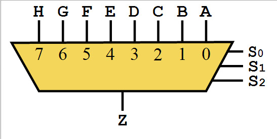

An electronic multiplexer makes it possible for several signals to share one device or resource, for example one A/D converter or one communication line, instead of having one device per input signal.
Flip-Flop:
A flip-flop is a circuit capable of two stable states and represents a single bit.
Registers:
A register is a group of flip-flops that stores a bit pattern. A register on the FPGA has a clock, input data, output data, and enable signal port. Every clock cycle, the input data is latched, stored internally, and the output data is updated to match the internally stored data.
Look-Up Table (LUT):
A LUT is a collection of logic gates hard-wired on the FPGA. LUTs store a predefined list of outputs for every combination of inputs and provide a fast way to retrieve the output of a logic operation
Block RAM:
It is block memory, it is RAM that is embedded throughout the FPGA for storing data. The block RAM can be SRAM or memory logic array block (MLAB).

FPGA:
Logic resources are resources on the FPGA that can perform logic functions. Logic resources are grouped in slices to create configurable logic blocks. A slice contains a set number of LUTs, flip-flops and multiplexers. The logic resources can be logic blocks, IO blocks, programmable routing block; they are the building blocks of FPGA.
Functional simulation - before design compilation
Timing simulation - after design compilation

LCB - LAB Control Block
ALE - Aggregate Logic Elements
Combinational Circuit:
Combinational logic circuits implement Boolean functions. Boolean functions are mappings of input bit strings to output bit strings. So, it means that if you feed in an input to a circuit, say, 000, then look at its output, and find that it is, 1, then the output will always be 1 for that circuit, if 000 is the input. Meaning 000 is mapped to 1. Combinational circuit are functions of their inputs, and are NOT based on clocks.
Sequential Circuit:

Unlike combinational logic, sequential circuits have state, which means basically, sequential circuits have memory. The state logic is implemented with flip flops. The main difference between sequential circuits and combinational circuits is that sequential circuits compute their output based on input and state, and that the state is updated based on a clock.
Verilog:
Verilog is case sensitive.
Reg and Wire
reg can store value and drive strength. It can be used for modeling both combinational and sequential circuit.
wire cannot store a value, it can be assigned a value, and used for connecting output port to the actual driver. it is used for making combinational circuit.
reg array:
verilog thinks in bits.
reg [7:0] datain_reg; /* 8x1 bit reg */
reg datain_reg[0:7]; /* An 8-bit reg */
reg [7:0] datain_reg[0:3]; /* 8x4 bit reg */
reg [7:0] datain_reg[0:7]; /* 8x8 bit reg */
wire [7:0] dataout_wire; /* 8x1 bit wire */
Use assign with wire:
assign dataout_wire[0]= 1'b0;
We can compare wire and reg array value:
reg [7:0] datain_reg;
wire [7:0] dataout_reg;
reg result;
if (datain_reg[i] != dataout_wire [i])
begin
result = 1'b0;
end
Always block
always @(a) /*level-trigger*/
always @(posedge a) /*edge-trigger for positive transation*/
valid for the following positive transition.
x -1
0-1
?-1
always @(posedge clk)
begin
q <= d
x<=q
z<=x
end
for non blocking statement, it will execute in sequence, but result is not available immediately.
Blocking and Nonblocking Statements
One can use the nonblocking statement whenever you want to make several register assignments within the same time step without regard to order or dependence upon each other
module block_nonblock(); reg a, b, c, d , e, f ; // Blocking assignments initial begin a = #10 1'b1;// The simulator assigns 1 to a at time 10 b = #20 1'b0;// The simulator assigns 0 to b at time 30 c = #40 1'b1;// The simulator assigns 1 to c at time 70 end // Nonblocking assignments initial begin d <= #10 1'b1;// The simulator assigns 1 to d at time 10 e <= #20 1'b0;// The simulator assigns 0 to e at time 20 f <= #40 1'b1;// The simulator assigns 1 to f at time 40 end endmodule |
Subscribe to:
Posts (Atom)