How to know if remote TCP device is down?
By default, TCP blocking socket will block when remote TCP device is down. We can use TCP KEEPALIVE to check:
setsockopt(SOL_SOCKET, SO_KEEPALIVE,...);
and set the TCP keep alive settings:
sysctl -w net.ipv4.tcp_keepalive_intvl = 10
sysctl -w net.ipv4.tcp_keepalive_time = 30
sysctl -w net.ipv4.tcp_keepalive_probes = 2
Then, the socket recv() function will return -1 when remote device is down.
Friday, 22 June 2012

Thursday, 10 May 2012
Shut it down
Graceful shutdown of Linux system to prevent hard disk ext2 file system corruption.
"/usr/local/bin/msp_int_handler" will call "init 0" to do graceful shutdown.
311 /************************************************************************
312
313 Previous
314 Implementation : Previously MSP was not generating the interrupt, and switching off
315 the power modules when Power button is switched off.
316
317 Description : Handling of the interrupt from MSP. When the power button is
318 off, then MSP generates an interrupt to MPC for gracefully shutdown.
319 The interrupt handler calls an userspace program called 'msp_int_handler'.
320
321
322
323 ************************************************************************/
324
325 static irqreturn_t msp_interrupt_handler(int gpio_irq,void *ignored);
326
327 static irqreturn_t msp_interrupt_handler(int gpio_irq,void *ignored) {
328
329 wake_up_interruptible(&msp_event);
330 msp_flag = 1;
331
332 return 1;
333 }
334
335 static int msp_interrupt_thread(void *ptr) {
336
337 char *argv[] = {"/usr/local/bin/gpio_test", "2", NULL };
338 char *envp[] = {"HOME=/", "PATH=/sbin:/usr/sbin:/bin:/usr/local/bin:", NULL };
339 int ret;
340
341 wait_event_interruptible(msp_event, msp_flag == 1);
342
343 printk("<msp-interrupt> got interrupt from MSP\n");
344
345 ret = call_usermodehelper("/usr/local/bin/msp_int_handler", argv, envp, UMH_WAIT_EXEC);
346
347 if (ret) {
348 printk("<msp-interrupt> call_usermodehelper is not successful \n");
349 } else {
350 printk("<msp-interrupt> call_usermodehelper is successful \n");
351 }
352
353 return 0;
354 }
355
356 static int msp_interrupt_thread_init(void)
357 {
358 int ret=0;
359 int virq;
360 #define SICRL_OFFSET 0x0114 /* SICR offset in IMMRBAR space */
361 __be32 __iomem *psicr = ioremap(get_immrbase() + SICRL_OFFSET, 4);
362 u32 sicr;
363 #define IRQ5_INTERRUPT_NUMBER 21
364
365 sicr = in_be32(psicr);
366
367 printk(" Before SICRL Register value : 0x%x \n",sicr);
368
369 sicr &= 0xFE7FFFFF; //clearing the bits 7 & 8 for IRQ5
370
371 out_be32(psicr, sicr);
372
373 sicr = in_be32(psicr);
374
375 printk(" After SICRL Register value : 0x%x \n",sicr);
376
377 // interrupt line from MSP to MPC for the power failure or power button press
378 virq = vinetic_map_irq(IRQ5_INTERRUPT_NUMBER);
379
380 if (request_irq(virq, &msp_interrupt_handler, 0, "MSP_IRQ", (void *)0))
381 printk(KERN_ERR "pmu: can't get irq %d" " (MSP to MPC)\n", virq);
382 else
383 printk("request_irq for IRQ5 is success with virtual IRQ %d",virq);
384
385 /* Wait Q initialization */
386
387 init_waitqueue_head(&msp_event);
388 printk(" msp interrupt thread init \n\n");
389 msp_interrupt_task = kthread_run(msp_interrupt_thread, NULL, "msp_interrupt_thread");
390
391 return ret;
392 }
393
394
395
396 static void __exit msp_interrupt_exit(void)
397 {
398 printk(" fact default module exit \n ");
399 }
400
401 module_init(msp_interrupt_thread_init);
402 module_exit(msp_interrupt_exit);
"/usr/local/bin/msp_int_handler" will call "init 0" to do graceful shutdown.
311 /************************************************************************
312
313 Previous
314 Implementation : Previously MSP was not generating the interrupt, and switching off
315 the power modules when Power button is switched off.
316
317 Description : Handling of the interrupt from MSP. When the power button is
318 off, then MSP generates an interrupt to MPC for gracefully shutdown.
319 The interrupt handler calls an userspace program called 'msp_int_handler'.
320
321
322
323 ************************************************************************/
324
325 static irqreturn_t msp_interrupt_handler(int gpio_irq,void *ignored);
326
327 static irqreturn_t msp_interrupt_handler(int gpio_irq,void *ignored) {
328
329 wake_up_interruptible(&msp_event);
330 msp_flag = 1;
331
332 return 1;
333 }
334
335 static int msp_interrupt_thread(void *ptr) {
336
337 char *argv[] = {"/usr/local/bin/gpio_test", "2", NULL };
338 char *envp[] = {"HOME=/", "PATH=/sbin:/usr/sbin:/bin:/usr/local/bin:", NULL };
339 int ret;
340
341 wait_event_interruptible(msp_event, msp_flag == 1);
342
343 printk("<msp-interrupt> got interrupt from MSP\n");
344
345 ret = call_usermodehelper("/usr/local/bin/msp_int_handler", argv, envp, UMH_WAIT_EXEC);
346
347 if (ret) {
348 printk("<msp-interrupt> call_usermodehelper is not successful \n");
349 } else {
350 printk("<msp-interrupt> call_usermodehelper is successful \n");
351 }
352
353 return 0;
354 }
355
356 static int msp_interrupt_thread_init(void)
357 {
358 int ret=0;
359 int virq;
360 #define SICRL_OFFSET 0x0114 /* SICR offset in IMMRBAR space */
361 __be32 __iomem *psicr = ioremap(get_immrbase() + SICRL_OFFSET, 4);
362 u32 sicr;
363 #define IRQ5_INTERRUPT_NUMBER 21
364
365 sicr = in_be32(psicr);
366
367 printk(" Before SICRL Register value : 0x%x \n",sicr);
368
369 sicr &= 0xFE7FFFFF; //clearing the bits 7 & 8 for IRQ5
370
371 out_be32(psicr, sicr);
372
373 sicr = in_be32(psicr);
374
375 printk(" After SICRL Register value : 0x%x \n",sicr);
376
377 // interrupt line from MSP to MPC for the power failure or power button press
378 virq = vinetic_map_irq(IRQ5_INTERRUPT_NUMBER);
379
380 if (request_irq(virq, &msp_interrupt_handler, 0, "MSP_IRQ", (void *)0))
381 printk(KERN_ERR "pmu: can't get irq %d" " (MSP to MPC)\n", virq);
382 else
383 printk("request_irq for IRQ5 is success with virtual IRQ %d",virq);
384
385 /* Wait Q initialization */
386
387 init_waitqueue_head(&msp_event);
388 printk(" msp interrupt thread init \n\n");
389 msp_interrupt_task = kthread_run(msp_interrupt_thread, NULL, "msp_interrupt_thread");
390
391 return ret;
392 }
393
394
395
396 static void __exit msp_interrupt_exit(void)
397 {
398 printk(" fact default module exit \n ");
399 }
400
401 module_init(msp_interrupt_thread_init);
402 module_exit(msp_interrupt_exit);
Wednesday, 28 March 2012
Web Application System Setup and Architecture
We can run web applications from embedded device. There are 3 ways to access the web applications.
1) Internal network, such as using http://192.168.1.1
This is straight forward. Devices connected internally through the Local Area Network are able to access the embedded device, eg. using the embedded device internal IP address of 192.168.1.1.
2) Dynamic DNS, such as using http://victor.dyndns-blog.com
Devices connected through Internet, access the embedded device via Dynamic DNS. The embedded device needs to run a dynamic DNS client, such as inadyn. inadyn supports www.dyndns.org. The user needs to register a hostname on www.dyndns.org. The hostname will point to the dynamic IP address of the embedded device.
3) Apache Web services, such as using http://service.victor.com
Deployed the web application front-end on Apache web services, the Apache web services will do reverse proxy to the web applications back-end on the embedded device. The front-end can be developed using Javascript, JQuery, SQL, Java server application such as Tomcat.
Setting up web applications on embedded device:
1) install php and lighttpd
PHP is an HTML-embedded scripting language. The goal of the language is to allow web developers to write dynamically generated pages quickly.
Lighttpd is a web server built for embedded systems.
2) setup php.ini
3) setup lighttpd.conf
fastcgi.server = ( ".php" =>
( "localhost" =>
(
"socket" => "/tmp/php-fastcgi.socket",
"bin-path" => "/usr/bin/php-cgi"
)
)
)
url.rewrite-once = (
"^/z/$" => "/z/app/webroot/",
"^/z/home/(.*)" => "/z/home/$1",
"^/z/(js|ico|gif|jpg|png|css)/(.*)" => "/z/app/webroot/$1/$2",
"^/z/(.*)$" => "/z/app/webroot/index.php?url=$1"
)
4) install cakephp
CakePHP is a free, open-source, rapid development framework for PHP. It helps programmers to create web applications.
5) setup cakephp
Modify routes.app
Router::connect('/devices', array('controller' => 'devices', 'action' => 'index'));
Router::connect('/devices/:action/*', array('controller' => 'devices'));
6) Install sqlite database
Sqlite is a light weight SQL database engine
Web applications access to Bluetooth devices
Imagine there are two ways, one on right hand side, read direct from bluetooth devices, the other on left hand side, read from database on embedded device.

1) Internal network, such as using http://192.168.1.1
This is straight forward. Devices connected internally through the Local Area Network are able to access the embedded device, eg. using the embedded device internal IP address of 192.168.1.1.
2) Dynamic DNS, such as using http://victor.dyndns-blog.com
Devices connected through Internet, access the embedded device via Dynamic DNS. The embedded device needs to run a dynamic DNS client, such as inadyn. inadyn supports www.dyndns.org. The user needs to register a hostname on www.dyndns.org. The hostname will point to the dynamic IP address of the embedded device.
3) Apache Web services, such as using http://service.victor.com
Deployed the web application front-end on Apache web services, the Apache web services will do reverse proxy to the web applications back-end on the embedded device. The front-end can be developed using Javascript, JQuery, SQL, Java server application such as Tomcat.
Setting up web applications on embedded device:
1) install php and lighttpd
PHP is an HTML-embedded scripting language. The goal of the language is to allow web developers to write dynamically generated pages quickly.
Lighttpd is a web server built for embedded systems.
2) setup php.ini
3) setup lighttpd.conf
fastcgi.server = ( ".php" =>
( "localhost" =>
(
"socket" => "/tmp/php-fastcgi.socket",
"bin-path" => "/usr/bin/php-cgi"
)
)
)
url.rewrite-once = (
"^/z/$" => "/z/app/webroot/",
"^/z/home/(.*)" => "/z/home/$1",
"^/z/(js|ico|gif|jpg|png|css)/(.*)" => "/z/app/webroot/$1/$2",
"^/z/(.*)$" => "/z/app/webroot/index.php?url=$1"
)
4) install cakephp
CakePHP is a free, open-source, rapid development framework for PHP. It helps programmers to create web applications.
5) setup cakephp
Modify routes.app
Router::connect('/devices', array('controller' => 'devices', 'action' => 'index'));
Router::connect('/devices/:action/*', array('controller' => 'devices'));
6) Install sqlite database
Sqlite is a light weight SQL database engine
Web applications access to Bluetooth devices
Imagine there are two ways, one on right hand side, read direct from bluetooth devices, the other on left hand side, read from database on embedded device.
Thursday, 1 March 2012
IP Port Forwarding
check:
cat /proc/sys/net/ipv4/ip_forward
/usr/sbin/iptables -t nat -A PREROUTING -p tcp --dport 81:81 -j DNAT --to 192.168.60.10:80
cat /proc/sys/net/ipv4/ip_forward
enable:
echo "1" > /proc/sys/net/ipv4/ip_forward
Example iptables rules: (forward port 81 to 192.168.60.10:80)
/usr/sbin/iptables -A FORWARD -p tcp --dport 80:80 -m state --state NEW,ESTABLISHED,RELATED -j ACCEPT/usr/sbin/iptables -t nat -A PREROUTING -p tcp --dport 81:81 -j DNAT --to 192.168.60.10:80
Thursday, 17 November 2011
PCI Bus
Introduction
In theory, there can be 256 PCI bus segments, 32 PCI device per PCI bus, and 8 PCI function per PCI device. One PCI device can have multi config space, depending on the multi-functionality of the device.For one PCI function, the size of PCI config space is 256 bytes. First 16 32-bits (64Bytes) is called PCI config header. The remaining 48 32-bits is the device specific config registers. The theoretical maximum PCI config space on a system is 256x32x8x256 Bytes = 16MB. Two to power of 24 is 16MB. We need 24-bits to uniquely identify a PCI device/function on the PCI bus.Five key signals: FRAME, IRDY, TRDY, STOP, DEVSEL. Master drives FRAME and IRDY. Target drives TRDY, STOP and DEVSEL. All are active low signal. FRAME is the first signal master asserts low. DEVSEL is the first signal target asserts low.
Access to PCI Base Address Register (BAR):
You can write directly to BAR register. To find out the size of BAR register, do the followingWrite 0xFFFFFFFF to BAR register
Read back from the BAR register
If the value is 0xFFFFF000, then the size of that address space by BAR register is 4K.
Parity Bit and Perr Timing:
Parity Bit is set one clock cycle after the data is ready, Perr is set two clock cycles after the data is ready to be read. There are two ways to simulate parity error on PCI bus; by triggering the wrong parity bit (Par), or by asserting Perr or Serr signal. On triggering the wrong parity bit, either 1) Azusa acts as initiator and read the data, or 2) Azusa acts as target and PCI master write to it. Agilent PCI tester provides options to set the parity bit PAR to the wrong value.Looking at case 1), example of scipt for Agilent PCI tester as master:
{
   m_xact(busaddr = 1000000\h, cmd = mem_write);
   m_data(data = 11111111\h, dwrpar);
   m_last(data = 8f548f53\h);
}
Here 0x1000000 is the Bar0 address of Azusa PCI controller, "dwrpar "instructs the PCI master to set parity bit to the wrong value, for write trasnfer.The waveform when Azusa acts as target and a PCI tester as Master, writes to it:
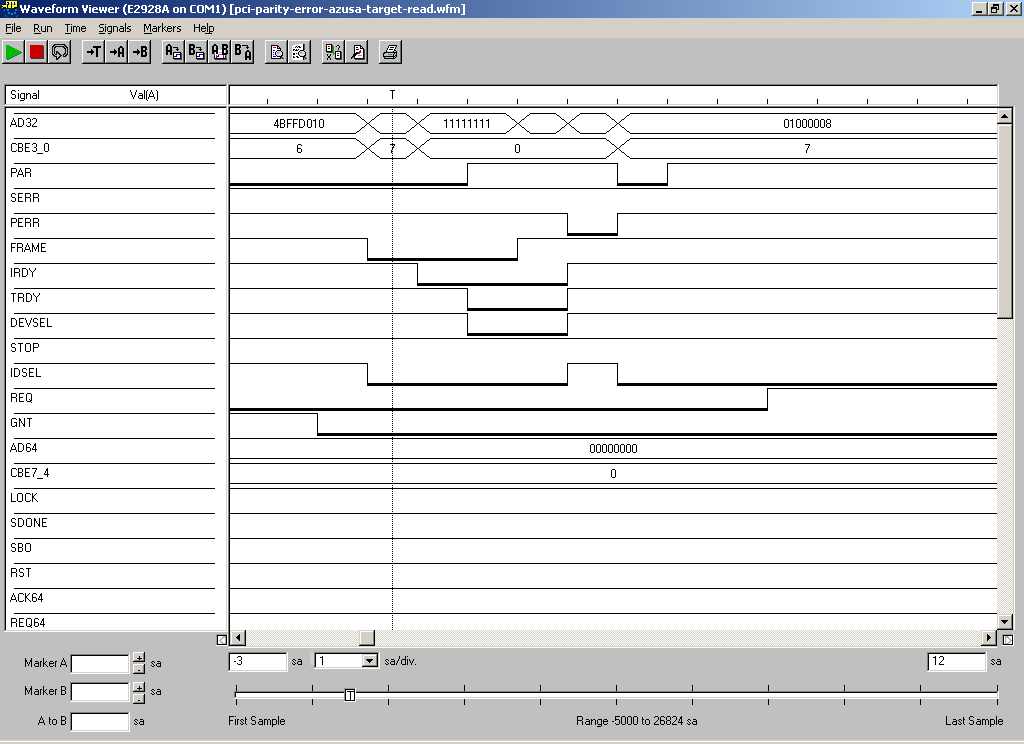
And now case 2), example of script for Agilent PCI tester as target:
{
 t_attr(wrpar);
}
Here the "wrpar" instructs the PCI tester to respond with wrong parity bit, for read transfer.The second waveform when Azusa acts as initiator and read from PCI bus:

Type 0 configuration address phase:
PCI CONFIG_ADDRESS register:
We write this format to the PCI CONFIG_ADDRESS register. The enable bit indicates a configuration transaction. For a type 0 config transaction, the PCI controller will generate a PCI address on PCI AD lines based on the diagram below:

Example:

The bits from 31:11 in address word will be matched with IDSEL pin on PCI device.
An example of type 0 address: 0x80000010;
This address will select device with IDSEL pin tied to the AD31 address line. The "1" value in bit 4 will select Bar0 register (offset 4).
An example of type 0 address: 0x00004010;
This address will select device with IDSEL pin tied to the AD14 address line. The "1" value in bit 4 will select Bar0 register (offset 4).
The IDSEL pin is only applicable to type 0 confiuration transaction.
Type 1 configuration address phase:
For type 1 config transaction, the PCI host directly copies the content of the CONFIG_ADDRESS register onto the PCI AD lines during the address phase of a config access.Bus Classification:
There are two kinds of bus: synchronous and asynchronous. In Sync bus, there is a common CLK. For master to initiate request and target to respond, the timing will follow the common CLK. In Async bus, one use req/ack strobing. PCI bus is a sync bus where all transaction happens on the rising edge of the CLK; i.e. device will only "see/check" IRDY and TRDY at the rising edge of the clock. However, it uses IRDY and TRDY to co-ordinate between the master and target.
First created: November 26, 2004
Last Modified: June 14, 2007
Last Modified: June 14, 2007
Wednesday, 16 November 2011
Ethernet Information
Ethernet Information
Ethernet Protocol
Here is the diagram of ethernet PDU. The length of each field is shown in bits.

Preamble: 8 bytes.
Indicates that the frame is about to begin
Destination Address: 6 bytes.
MAC address of the destination node. May be unicast, multicast or broadcast.
Source Address: 6 bytes.
The unicast MAC address of the source node.
Type/Length: 2 bytes.
The number of bytes encapsulated OR the protocol type of the next higher protocol.
Data: Variable length, 46 to 1500 bytes.
FCS: Frame Check Sequence.
Ethernet Version 2 (also Version "II") is the original version also known as DIX, which stands for Digital, Intel, and Xerox, the vendor consortium who first created it. The IEEE 802.3 Ethernet standard was established some time later. The original Ethernet Version 2 frame varies slightly from the 802.3 Ethernet frame format in that a Type field, also referred to as Ethertype, is used in place of the Length field (also 2 bytes). The Type field is used to "steer" the information up the protocol stack to the next layer. Examples of Ethertype values are 0x0800 for IP and 0x0806 for Address Resolution Protocol (ARP). The 802.3 Ethernet frame has a Length field instead of a Type field, and an 802.2 LLC header in the payload field. The LLC header DSAP field indicates the protocol being carried and steers the frame to the appropriate process in the Network Layer, just as the EtherType field did in the Ethernet Version 2 frame. Another way of looking at this is that Ethernet frames have either a Length or a Type field. When using LLC, the field is Length-encoded. If not using LLC, the field is Type-encoded.
Jumbo Frame
Usually Jumbo Frame is made up of 9000 bytes (payload), 9018 bytes (including header).pitfalls: DONT_FRAGMENT bit in IP header solution: Station reconfigure its IP protocol stack for a smaller MTU
Ethernet Standards
IEEE 802.3 half-duplex Ethernet (CSMA/CD)IEEE 802.3x full-duplex Ethernet - PAUSE frame

IEEE 802.3u Fast Ethernet (100BASE-T)
IEEE 802.3z Gigabit Ethernet (1000BASE-X)
IEEE 802.3ab Gigabit Ethernet (1000BASE-T)
IEEE 802.3ac Ethernet VLANs
IEEE 802.3ae 10Gigabit Ethernet
TCP offload - shifting TCP/IP processing tasks to network adapters, removing server CPU out of I/O processing
TCP segment offloading (TSO) - offloading segmentation task of TCP layer from host CPU to NIC
How ICMP Packet is embedded in Ethernet Frame


The 14-byte ethernet header is omitted in this picture. The rest of the fields are:
8 Bytes LLC Header (including SNAP header)
20 Bytes IP Header
8 Bytes ICMP Header
56 Bytes ICMP Payload
4 bytes FCS
How 802.1X Packet is embedded in WiFi Mac Frame


This show an 802.1X packet in 802.11 radio link.
Ethernet Pinout
Here is the RJ-45 Receptacle Pinouts:Pin Description 1 TxD+ 2 TxD- 3 RxD+ 6 RxD-Here are instructions for building an Ethernet 10BaseT or 100BaseT crossover cable. The pinouts for an Ethernet crossover cable are as follows:

|  |
First Created: March 4, 2005
Last Modified: May 29, 2006
Last Modified: May 29, 2006


Monday, 14 November 2011
Low Level Assembly Stuffs
Low Level Assembly Stuffs
x86 Interrupts
Whenever external devices trigger the interrupt line, the CPU will notice the change of status in interrupt line, and update the interrupt status register. The CPU will then store the state info on the stack (for returning to current activities later), inspect the interrupt descriptor table (IDT), and jump to location pointed to by the IDT. The OS takes over from there. Subsequently, user-defined interrupt handler will be executed.
IDT is a data structure used by the x86 architecture in determining the correct response to interrupts and exceptions. IDT is setup by the OS, and can be anywhere in the memory. Use of the IDT can be triggered by three types of events: hardware interrupts, software interrupts and exceptions. In total, up to 256 of these can be defined, each with their own unique identifier which is called a descriptor. The IDT is an array of these 8-byte descriptors stored consecutively in memory and indexed by the interrupt vector. Vectors 0-15 are for processor generated exceptions (general protection fault, page fault, etc.). Vectors 16-31 are typically used for hardware interrupts, and higher vector numbers are only generated by software.
GNU Assembler Directives
All assembler directives have names that begin with a period (.). The rest of the name is made of letters, usually in lower case.
Local Symbol Names
.macro    mvRocClkDelay  clk, reg=r0, tmp=r1
 ldr     \reg, =\clk
 ldr     \tmp, =CNTMR_RELOAD_REG(0)
 str     \tmp, [\tmp]
1:
 ldr     \tmp, [\tmp]
 cmp     \tmp, #0
 bne     1b
.endm

bne  1b  - b is backwards,  1: is  local label
Macro
.macro mvMovReg mode=CPSR_MBIT_FIQ, orgmode=CPSR_MBIT_SVC, reg=r0, regno=14, dir=0
 msr  cpsr_c, #\mode
 .if (\dir==0)
 mov  r\regno, \reg
 .else
 mov  \reg, r\regno
 .endif
 msr  cpsr_c, #\orgmode
.endm

mode, orgmode, etc are macro parameters
\reg refers to parameter within macro
mode=CPSR_MBIT_FIQ, etc are default parameters
Special Dot Symbol
It assigns a value to ".", it is the same as a .org directive.
__asm__ __volatile__ (
     "ldr  %1, .+8  \n"
     "b  .+12  \n"
     ".long  0  \n"
     ".long  .+12  \n"
     "ldr  %0, .-4  \n"
     "sub  %0, pc, %0  \n"
     "add  %0, %0, %1 \n"
        :"=r"(tmp), "=r"(tmp1)
        );

b .+12 will jump to ldr %0, .-4
ldr %1, .+8 will load from the location of .long 0
.long .+12 will assign the address value of  "add %0, %0, %1\n" to
current location
AT&T Syntax versus Intel Syntax
The x86 assembly language has two main syntax branches: Intel syntax, originally used for documentation of the x86 platform, and AT&T syntax. Intel syntax is dominant in the Windows world, and AT&T syntax is dominant in the Unix world,
AT&T immediate operands are preceded by `$'; Intel immediate operands are un-delimited (Intel `push 4' is AT&T `pushl $4'). AT&T register operands are preceded by `%'; Intel register operands are un-delimited. AT&T absolute (as opposed to PC relative) jump/call operands are prefixed by `*'; they are un-delimited in Intel syntax.
AT&T and Intel syntax use the opposite order for source and destination operands. Intel is `add eax, 4'. AT&T is is `addl $4, %eax'.
In AT&T syntax the size of memory operands is determined from the last character of the instruction mnemonic. Mnemonic suffixes of `b', `w', `l' and `q' specify byte (8-bit), word (16-bit), long (32-bit) and quadruple word (64-bit) memory references. Intel syntax accomplishes this by prefixing memory operands (_not_ the instruction mnemonics) with `byte ptr', `word ptr', `dword ptr' and `qword ptr'. Thus, Intel `mov al, byte ptr FOO' is `movb FOO, %al' in AT&T syntax.
Immediate form long jumps and calls are `lcall/ljmp $SECTION, $OFFSET' in AT&T syntax; the Intel syntax is `call/jmp far SECTION:OFFSET'. Also, the far return instruction is `lret $STACK-ADJUST' in AT&T syntax; Intel syntax is `ret far STACK-ADJUST'.
The AT&T assembler does not provide support for multiple section programs. Unix style systems expect all programs to be single sections.
Register Naming
The x86 registers consist of:* the 8 32-bit registers `%eax' (the accumulator),`%ebx',`%ecx', `%edx', `%edi', `%esi', `%ebp' (the frame pointer), and `%esp' (the stack pointer).
* the 8 16-bit low-ends of these: `%ax', `%bx', `%cx', `%dx', `%di', `%si', `%bp', and `%sp'.
* the 8 8-bit registers: `%ah', `%al', `%bh', `%bl', `%ch', `%cl', `%dh', and `%dl' (These are the high-bytes and low-bytes of `%ax',`%bx', `%cx', and `%dx')
* the 6 section registers `%cs' (code section), `%ds' (data section), `%ss' (stack section), `%es', `%fs', and `%gs'.
* the 3 processor control registers `%cr0', `%cr2', and `%cr3'.
* the 6 debug registers `%db0', `%db1', `%db2', `%db3', `%db6', and `%db7'.
* the 2 test registers `%tr6' and `%tr7'.
* the 8 floating point register stack `%st' or equivalently `%st(0)', `%st(1)', `%st(2)', `%st(3)', `%st(4)', `%st(5)', `%st(6)', and `%st(7)'.
These registers are overloaded by 8 MMX registers
`%mm0', `%mm1', `%mm2', `%mm3', `%mm4', `%mm5', `%mm6' and `%mm7'.
* the 8 SSE (Streaming SIMD Extensions) registers registers
`%xmm0', `%xmm1', `%xmm2', `%xmm3', `%xmm4', `%xmm5', `%xmm6' and `%xmm7'.
The AMD x86-64 architecture extends the register set by:
* enhancing the 8 32-bit registers to 64-bit: `%rax' (the accumulator), `%rbx', `%rcx', `%rdx', `%rdi', `%rsi', `%rbp' (the frame pointer), `%rsp' (the stack pointer)
* the 8 extended registers `%r8'-`%r15'.
* the 8 32-bit low ends of the extended registers:`%r8d'-`%r15d'
* the 8 16-bit low ends of the extended registers:`%r8w'-`%r15w'
* the 8 8-bit low ends of the extended registers: `%r8b'-`%r15b'
* the 4 8-bit registers: `%sil', `%dil', `%bpl', `%spl'.
* the 8 debug registers: `%db8'-`%db15'. * the 8 SSE registers: `%xmm8'-`%xmm15'.
First created: May 12, 2004
2nd Edition: April 23, 2007
Last update: Nov 14, 2008
2nd Edition: April 23, 2007
Last update: Nov 14, 2008
TCP Demystified
TCP Header
This is the TCP Header Format. The basic TCP header is 20 bytes in length. 0 1 2 3
0 1 2 3 4 5 6 7 8 9 0 1 2 3 4 5 6 7 8 9 0 1 2 3 4 5 6 7 8 9 0 1
+-+-+-+-+-+-+-+-+-+-+-+-+-+-+-+-+-+-+-+-+-+-+-+-+-+-+-+-+-+-+-+-+
| Source Port | Destination Port |
+-+-+-+-+-+-+-+-+-+-+-+-+-+-+-+-+-+-+-+-+-+-+-+-+-+-+-+-+-+-+-+-+
| Sequence Number |
+-+-+-+-+-+-+-+-+-+-+-+-+-+-+-+-+-+-+-+-+-+-+-+-+-+-+-+-+-+-+-+-+
| Acknowledgement Number |
+-+-+-+-+-+-+-+-+-+-+-+-+-+-+-+-+-+-+-+-+-+-+-+-+-+-+-+-+-+-+-+-+
| Data | |U|A|P|R|S|F| |
| Offset| Reserved |R|C|S|S|Y|I| Window |
| | |G|K|H|T|N|N| |
+-+-+-+-+-+-+-+-+-+-+-+-+-+-+-+-+-+-+-+-+-+-+-+-+-+-+-+-+-+-+-+-+
| Checksum | Urgent Pointer |
+-+-+-+-+-+-+-+-+-+-+-+-+-+-+-+-+-+-+-+-+-+-+-+-+-+-+-+-+-+-+-+-+
| Options | Padding |
+-+-+-+-+-+-+-+-+-+-+-+-+-+-+-+-+-+-+-+-+-+-+-+-+-+-+-+-+-+-+-+-+
| data |
+-+-+-+-+-+-+-+-+-+-+-+-+-+-+-+-+-+-+-+-+-+-+-+-+-+-+-+-+-+-+-+-+
TCP Header Format
Source Port: 16 bitsThe source port number.
Destination Port: 16 bits
The destination port number.
Sequence Number: 32 bits
    The sequence number of the first data octet in this segment
    (except when SYN is present). If SYN is present the sequence
    number is the initial sequence number (ISN) and the first
    data octet is ISN+1.
Acknowledgement Number: 32 bits
    If the ACK control bit is set this field contains the value of
    the next sequence number the sender of the segment is expecting
    to receive.  Once a connection is established this is always
    sent.
Data Offset: 4 bits The number of 32 bit words in the TCP Header. This indicates
where the data begins. The TCP header (even one including
options) is an integral number of 32 bits long.
Reserved: 6 bits
Reserved for future use. Must be zero.Control Bits: 6 bits (from left to right):
    URG:  Urgent Pointer field significant
    ACK:  Acknowledgment field significant
    PSH:  Push Function
    RST:  Reset the connection
    SYN:  Synchronize sequence numbers
    FIN:  No more data from sender
Window: 16 bits
    The number of data octets beginning with the one indicated
    in the acknowledgment field which the sender of this segment
    is willing to accept.
Checksum: 16 bits The checksum field is the 16 bit one's complement of the one's
complement sum of all 16 bit words in the header and text. If a
segment contains an odd number of header and text octets to be
checksummed, the last octet is padded on the right with zeros to
form a 16 bit word for checksum purposes. The pad is not
transmitted as part of the segment. While computing the
checksum, the checksum field itself is replaced with zeros.
The checksum also covers a 96 bit pseudo header conceptually
prefixed to the TCP header. This pseudo header contains the
Source Address, the Destination Address, the Protocol, and TCP
length. This gives the TCP protection against misrouted segments.
This information is carried in the Internet Protocol and is
transferred across the TCP/Network interface in the arguments or
results of calls by the TCP on the IP.
+--------+--------+--------+--------+
| Source Address |
+--------+--------+--------+--------+
| Destination Address |
+--------+--------+--------+--------+
| zero | PTCL | TCP Length |
+--------+--------+--------+--------+
The TCP Length is the TCP header length plus the data length
in octets (this is not an explicitly transmitted quantity,
but is computed), and it does not count the 12 octets of the
pseudo header.
Urgent Pointer: 16 bits This field communicates the current value of the urgent
pointer as a positive offset from the sequence number in this
segment.
The urgent pointer points to the sequence number of the octet
following the urgent data. This field is only be interpreted
in segments with the URG control bit set.
Options: variable
Options may occupy space at the end of the TCP header and are a
multiple of 8 bits in length. All options are included in the
checksum.  An option may begin on any octet boundary. There are two
cases for the format of an option:
    Case 1:  A single octet of option-kind.

    Case 2:  An octet of option-kind, an octet of option-length,
             and the actual option-data octets.

The option-length counts the two octets of option-kind and
option-length as well as the option-data octets.

Note that the list of options may be shorter than the data offset
field might imply.  The content of the header beyond the
End-of-Option option must be header padding (i.e., zero).
A TCP must implement all options.
Currently defined options include (kind indicated in octal):

      Kind     Length    Meaning
      ----     ------    -------
       0         -       End of option list.
       1         -       No-Operation.
       2         4       Maximum Segment Size.


Specific Option Definitions

      End of Option List

        +--------+
        |00000000|
        +--------+
         Kind=0

        This option code indicates the end of the option list.  This
        might not coincide with the end of the TCP header according
        to the Data Offset field.  This is used at the end of all
        options, not the end of each option, and need only be used
        if the end of the options would not otherwise coincide with
        the end of the TCP header.

      No-Operation

        +--------+
        |00000001|
        +--------+
         Kind=1

        This option code may be used between options, for example,
        to align the beginning of a subsequent option on a word
        boundary. There is no guarantee that senders will use this
        option, so receivers must be prepared to process options
        even if they do not begin on a word boundary.

      Maximum Segment Size

        +--------+--------+---------+--------+
        |00000010|00000100|   max seg size   |
        +--------+--------+---------+--------+
         Kind=2   Length=4

      Maximum Segment Size Option Data:  16 bits

        If this option is present, then it communicates the maximum
        receive segment size at the TCP which sends this segment.
        This field must only be sent in the initial connection
        request (i.e., in segments with the SYN control bit set).
        If this option is not used, any segment size is allowed.
Padding: variable
    The TCP header padding is used to ensure that the TCP
    header ends and data begins on a 32 bit boundary.  The
    padding is composed of zeros.
TCP Overhead
As TCP is a connection-oriented protocol, this adds to the complexity and processing overhead of the protocol, these aspects include:
Connection establishment using the 3 Way Handshake, this involves a number of messages passing between the connection initiator and the connection responder prior to any data flowing between the two endpoints.
Acknowledgment of packets as they are received by the far end, adding to the message flow between the endpoints and thus the protocol load.
Checksum and Sequence number calculations - again a burden on a general purpose CPU to perform.
Sliding window calculations for packet acknowledgement and congestion control.
Connection termination.
TOE
TCP Offload Engine (TOE) is a technology used in network interface cards to offload processing of the entire TCP/IP stack to the network controller. It is primarily used with high-speed network interfaces, such as gigabit Ethernet and 10 gigabit Ethernet, where processing overhead of the network stack becomes significant.
TSO
TCP segmentation offloading (TSO) - reduce CPU overhead of TCP/IP on fast networks. the CPU can hand the NIC a block of data and a TCP header template, and then have the NIC produce a stream of TCP packets without requiring the CPU to touch the data at all. When large chunks of data are to be sent over a computer network, they need to be first broken down to smaller segments that can pass through all the network elements like routers and switches between the source and destination computers. This process is referred to as segmentation.
Segmentation is often done by the TCP protocol in the host computer. Offloading this work to the network card is called TCP segmentation offloading. With some intelligence in the NIC, the host CPU can hand over the 64 KB of data to the NIC in a single buffer, the NIC can break that buffer down into smaller segments of 1448 bytes, add the TCP, IP, and data link layer protocol headers -- according to a template provided by the host's TCP/IP stack -- to each segment, and send the resulting frames over the network. This significantly reduces the work done by the CPU.
First Created: 4 May 2007
SNMP Agent and HP Openview
SNMP Agent and HP Openview
1. SNMP Details
SNMP manager and agent communicate through UDP port 161. SNMP trap receiver listens to UDP port 162 for TRAP messages.
Message format for SNMPv1 and SNMPv2 GET, GET response, GET NEXT and SET; and SNMPv2 TRAP and INFORM is shown below:
| Version | Community | PDU |
| PDU | ||||
| PDU Type | Request ID | Error Status | Error Index | Variable Bindings |
SNMPv2 GET BULK PDU format is different.
PDU (GET BULK)
| ||||
| PDU Type | Request ID | Non repeaters | Max Repetitions | Variable Bindings |
Non repeaters specifies the number of supplied variables that should not be iterated over.
Max Repetitions specifies the maximum number of iterations over the repeating variables.
PDU Type:
- GET: A0
- GET NEXT: A1
- GET response: A2
- SET: A3
- TRAP (v1): A4:
- GET BULK (v2): A5
- INFORM (v2): A6
- TRAP (V2): A7
The encoding of SNMP messages follows the Basic Encoding Rules (BER). BER is part of ASN.1 standard. All SNMP messages follows the tag-length-value structure. The following graph shows the tag value.
| 0x30 - sequence |
| tag | length | value : sequence of fields |
| 0x02 - integer |
| tag | length | value : 0 (SNMPv1) |
| version |
| 0x04 - octet string |
| tag | length | value : octets |
| community string |
| tag - depends on PDU |
| tag | length | value : sequence of fields |
| SNMPv1 PDU |
In SNMP v1, SNMP GET operation is atomic, either all the values are retrieved or none of them are. SNMP SET operation is atomic too, either all the values are set or none of them are. SNMPv2 extends the SNMP protocol by defining:
- an SNMPv2 TRAP PDU
- an Inform message, which is basically a TRAP that gets ack
- a GET-BULK message,which is a souped up extension to GET-NEXT
- additional error status
- changes the way responses to GET and GET-NEXT are handled if one of the objects in the variable bindings cannot be retrieved.
SNMPV2 GET and GET-NEXT will return the object values that are available, even if some object values cannot be retrieved. SNMPv2 SET operation is still atomic.
SMIv2 introduces textual conventions. Textual conventions are refinements of basic data types. and textual conventions resolve to primitive data types. Example:
MacAddress ::= TEXTUAL-CONVENTION
    DISPLAY-HINT "1x:"
    STATUS       current
    DESCRIPTION
                 "..omitted..."
    SYNTAX       OCTET STRING (SIZE (6))
1.1 SNMPv1 TRAPThe SNMPv1 PDU format is shown below:
| PDU Type |
| 0xA4 | ent. | addr | generic | specific | ts | vb |
Some real case PDU formats in hexadecimal format is shown here:
Cold Start generic trap:
Sequence          30 82 00 21
Version           02 01 00
Community         04 06 70 75 62 6C 69 63
PDU Type          A4 14             (A4 is PDU type of SNMPv1 TRAP)
enterprise        06 01 00
agent address     40 04 0A 3E 55 00 (agent generating the trap)
generic           02 01 00          (00 is cold start)
specific          02 01 00          (00 means no specific trap)
time-stamp        43 01 02
variable bindings 30 00
Customised specific trap:
Sequence          30 82 00 2A
Version           02 01 00
Community         04 06 70 75 62 6C 69 63
PDU Type          A4 1D             (A4 is PDU type of SNMPv1 TRAP)
enterprise        06 0A 2B 06 01 04 01 E4 44 01 02 01
                        (1.3.6.1.4.1.xxxxx.1.2.1 is the ObjectID of the TRAP)
agent address     40 04 0A 3E 55 00 (agent generating the trap)
generic           02 01 06          (06 means enterprise specific)
specific          02 01 01          (01 is the number of specific TRAP)
time-stamp        43 01 09
variable bindings 30 00
2. SNMP Agent
An SNMP agent(agent) responds to SNMP requests, which are sent from SNMP manager application(manager). At the same time, an agent sends out SNMP TRAP messages to manager when pre-defined conditions has been reached.
The design of agent can be divided into three functional areas:
- transport stack
- protocol engine
- access to management information
- monolithic approach - where the transport stack, protocol engine and management info access are combined together.
- extensible approach - where the agent and management info access are separated, the linkage of agent and management info access are delayed until load time or run time.
- SMUX in RFC 1227 - SNMP multiplexing protocol
- SNMP-DPI in RFC 1228 and RFC 1592 - SNMP Distributed Protocal Interface
- AgentX in RFC 2741 and RFC 2742
- EMANATE technology from SNMP Research
- SNMP++ - a set of C++ classes for writing manager
- AGENT++ - a set of C++ classes for writing agent
- NET-SNMP - a set of C APIs for writing manager and agent
2.1 Using AGENT++ to write an agent
AGENT++ v3.5.6 and SNMP++ v3.2.1 will be used in this project. SNMP++ is a set of C++ classes that contains the SNMP protocal engine. For transport stacks, SNMP++ makes use of the Windows socket library or Linux socket library calls. AGENT++ extends SNMP++ by providing the access methods to management information that an agent needs.
AGENT++ is a set of C++ classes which provides a complete protocol engine and dispatch table for the development of SNMP agents. AGENT++ is a multilingual API which supports SNMPv1, SNMPv2c, and SNMPv3. It provides various C++ classes implementing prototypes for scalar and table SNMP managed objects that can be customized by derivation. Additional classes support the development of proxy agents as well as sending notifications.
At the same time, AgentGen v1.8.6 is used. It is a tool to generate C++ source code from SNMP MIB files. The generated code makes used of the AGENT++ library, and thus cannot be compiled without it.
AgentGen Code Generation Steps:
- cd to agentgen directory
- % mkdir mibrepository
mibrepository is a directory for storing compiled MIB files in intermediate format - % agentgen ../mibrepository init
initialise the repository - % agentgen ../mibrepository load miblist.txt
load a list of MIB files to the repository - % agentgen ../mibrepository add sir-line-mib.txt
add a single MIB file to the repository - % agentgen ../mibrepository generate SIR-LINE-MIB h 3.5 > /home/sir_line_mib.h
generate a header file, using AGENT++ v3.5 - % agentgen ../mibrepository generate SIR-LINE-MIB c 3.5 > /home/sir_line_mib.cpp
generate a implementation file, using AGENT++ v3.5
The generated code from AgentGen v1.8.6 is guaranteed to work with AGENT++ v3.5.6 and SNMP++ v3.2.1. There is no such guarantee on the generated code from other lower/earlier AgentGen version.
SNMP Agent Compilation Procedure with MSVC++ 6.0 on W2000:
- Compile SNMP++ library
- modify config.h to comment out _SNMPv3 definition
- Compile AGENT++ library
- Create a new project
- Set up VC++ include path
- Tools->Options
- put in AGENT++ and SNMP++ include path(must put them above standard VC++ include path)
- Add in library modules
- Project->Settings->Link Tab
- add in snmp++.lib, agent++.lib, wsock32.lib for debug version
- add in snmp++.lib, agent++.lib, wsock32.lib, and libc.lib and msvcrt.lib for release version
- Setup Vc++ library path
- Tools->Options
- put in AGENT++ and SNMP++ lib path(any order)
- Build the project
- If there is LNK4098 warning, goto
- Project->Settings->Link Tab
- In Project Options: add in /verbose:lib to determine which libraries the linker is searching
- add in /nodefaultlib:"libcd.lib" to ignore the specific library
- If SNMP agent cannot execute, goto
- Control Panel->Administrative Tools->Services and stop the SNMP Service(It is because the SNMP Service uses UDP port 161, same as SNMP agent, therefore SNMP agent cannot bind the same port again.)
3. HP Openview
HP Openview is a complete portfolio of software solutions and services. It covers a broad area of management topics, including:
- Network/Internet Management
- Network Node Manager (NNM)
- NNM Extended Topology
- NNM Multicast
- Performance Insight for Networks
- Problem Diagnosis
- Smart Plug-ins (SPIs) for Data Network Devices
- TeMIP
- Trend Performance manager
- Systems Management
- Advanced Security
- GlancePlus
- Operations for UNIX/Windows
- System SPIs
- Performance (Manager, Monitor, Agents)
- Application Management
- Integration Tools
- Internet Services
- Application SPIs
- Web Transaction Observer
- Storage and Data Management
- Data Protector
- Omniback II
- Storage Area Manager
- Customer Service Management
- Reporter
- Service Activator
- Service Desk
- Service Navigator
- Service Usage Management
- Dynamic Netvalue Analyzer
- Internet Usage Manager
Network Node Manager
HP Openview Network Node Manager (NNM) is the focus of this discussion. It features:- visual display of the network - map symbols change color to indicate if something is wrong
- data collection of critical network information - this data can be graphed in real-time.
- event handling - events are sent to NNM's event browser
- remote access via the web
- provide troubleshooting tools to help users resolve problems
- maintains a relational database - data can be exported for historical analysis using any choice of statistical programs
- out of the box reports on the health of the network - provides easy access to report generation
NNM Maps and Submaps
Maps
A map is a collection of OpenView Windows (OVW) objects and their relationships. Users don't view maps directly. They view windows called submaps that display a subset of map information. Users can create several maps, among all the maps that might exist, users can select one map to be the open map. The open map is the only map that can be updated. Only one map can be open at a time in any given OVW session.
Submaps
A submap is a collection of related symbols that are displayed in one graphical window. Submaps essentially provide a view into the map object space. Each submap displays a different perspective of the information in the map, with the submaps typically organized in a hierarchical fashion.


The NNM data warehouse is a relational database (RDBMS) provided with NNM. NNM stores a copy of the information from the NNM operational databases into the data warehouse. The data warehouse information is accessible with standard SQL statements using ODBC tools. The information in the NNM event database is discarded when a certain volume is reached. Information copied to the data warehouse is retained for as long as we wish. The limit to the size of the data warehouse is up to us.

Event Correlation System (ECS)
NNM determines which node symbol to be used for each node by referencing two configuration files:
install_dir\fields\C\ovw_fields
The most common method for users to navigate through submaps is double-clicking on explodable symbols. Double-clicking on an explodable symbol will cause a submap to be displayed, if one exists. This submap is called the child submap. The object associated with the explodable symbol is called the parent object. The child submap shows all the objects contained within the parent object. The submap on which the parent object is represented is called the parent submap.
Submap context provides a way for application developers to describe the intended use for the submap. This context is then used to selectively add and remove menu items for the submap.
eg. Map->Submap->Properties, Context Tab,
    isInternet
    isIP
When a developer uses the application registration files to customize a menu, the developer defines a menu placement rule that specifies the contexts in which the menu item can be placed. When a submap is opened, the full list of possible menu items is checked. If a menu item's placement rule evaluates as true for the given submap's context, it is added to that submap's menus.
Here is a diagram of the relationship between maps and submaps.

In the diagram, submap 1 is the root submap for the map. Submaps 3A and 3B are child submaps of the objects whose symbols appear in submap 3. Submap 2 is an orphaned submap. Each submap contains symbols that represent objects on the map. The map is a collection of objects and their relationships, and submaps are the vehicle by which this map information is displayed.
NNM Objects and Fields
In NNM, fields are object attributes stored in the HP OpenView Windows (OVW) object database. Fields are the building blocks from which objects are constructed. Fields are created using either the field registration file (FRF) or the programming way.
Each field definition is uniquely identified by a field ID. Fields can contain a single data element, or they can contain a list of data elements of the same type.
By themselves, fields are not very useful. Only after a field is associated with an object can you perform the real manipulation of data, such as setting or retrieving field values. Fields can contain data only when they are associated with objects.
In NNM, an object is an internal representation of a logical or physical entity or resource that exists somewhere in a computer network. An NNM object consists of a unique object identifier and a set of fields that specify all the characteristics of the object.
The OVW object database manages all object and field information. All OVW maps use the same object database. The object database is implemented as a stand-alone module that works in conjunction with the rest of OVW. Entries in the OVW object database persist across OVW sessions. Fields and objects created in one OVW session are available to all other applications in all OVW sessions.
NNM Symbols
Symbols are presentation elements, while objects are underlying database elements that represent real-world objects. A symbol is a graphical representation of an object as it appears on a submap of a particular map. An object may be represented by multiple symbols. As presentation elements, symbols have attributes that are unrelated to the objects they represent. Important symbol attributes include:
- label : The symbol label is a textual string that is displayed at the bottom of each symbol. The symbol label is provided as a convenience to users. The label does not have to be unique.
- symbol type : The symbol type determines the graphical representation of the symbol. The term symbol type is a convenient way of referring to the symbol class/subclass pair that defines how the symbol is displayed.
- behavior : A symbol can either be explodable or executable. This characteristic determines what will happen when the user double-clicks on the symbol. By default, symbols added to a map are explodable in nature. That is, double clicking on an explodable symbol results in the display of the child submap. Applications and users can make a symbol executable. Double clicking on an executable symbol results in the invocation of an action provided by an application.
- position : The submap layout algorithm controls how symbols are placed on a submap. The layout algorithm is chosen during submap creation, and is fixed for the life of the submap.
- status : Each symbol within NNM can display status information through the use of color. Each of the different possible status values has an associated color that indicates the status of the symbol.
- status source : symbols can receive status from one of three sources:
- Status by Object: This status source causes the symbol to reflect the status for the underlying object.
- Compound Status: This status source can be used for a symbol whose underlying object serves as a parent object for a child submap.
- Status by Symbol: This status source lets a specific symbol instance receive status directly from an application. Use this status source if the application has the exclusive responsibility for setting status for the specific symbol instance.
- presentation : Symbol presentation provides visual cues to emphasize or to de-emphasize a symbol.
NNM Services
There are two types of services in the operation of NNM:
- Background services that run continuously independent of whether ovw is running.
- Foreground services that run while ovw is running.
NNM background services:
The following services and files are involved with the startup of NNM.
- ovstart: Starts the various services that make up the NNM.
- ovspmd: Launches and manages all background services. ovspmd interacts with the user commands ovstart, ovstop, ovstatus, ovpause, and ovresume, and performs the appropriate actions on the background services.
- ovsuf: Contains the configuration information for ovspmd. Each entry in ovsuf is created by ovaddobj from information in the LRF (Local Registration File).
The following services run in the background during regular operation.
- netmon: Polls SNMP agents to discover your network, and then detects topology, configuration, and status changes in the network.
- ovactiond: Receives events from pmd and executes commands.
- ovalarmsrv: Provides event information to Java-based Alarm Browsers.
- ovcapsd: Listens for new nodes and checks them for remote DMI capabilities, web-manageability, and web server capabilities.
- ovhpas: Maintains topology and node status information for NNM Dynamic views.
- ovrequestd: Executes the reports and data warehouse exports according to a predefined schedule. Once a report is configured, ovrequestd starts executing the exports and the reports.
- ovsessionmgr: Manages users' web sessions. ovsessionmgr.exe is started by ovstart.
- ovtopmd: Maintains the network topology database. The topology database is a set of files that stores netmon polling status and information about network objects, including their relationships and status. ovtopmd reads the topology database at start-up.
- ovtrapd: Receives SNMP traps and forwards them to pmd. ovtrapd also responds to SNMPv2 requests.
- ovuispmd: Manages the NNM user interface services and distributes relevant ovspmd requests to each instance of ovw that is running. ovuispmd must be running for ovw to be started, and should be running whenever ovspmd is running.
- ovwdb: Controls the object database. The object database stores semantic information about objects.
- pmd: Receives and forwards events, and logs events to the event database. pmd also forwards events from the network to other applications that have connected to pmd using the SNMP API.
- snmpCollect: Collects MIB data and performs threshold monitoring. snmpCollect stores the data it collects in the install_dir\databases\snmpcollect directory and sends threshold events to pmd.
Foreground Services
This section describes the NNM foreground services that may be running after you execute ovw.
- ipmap: Runs under ovw to automatically draw IPX and IP topology maps representing your network.
- ovw: The service that provides map drawing, map editing, and menu management. When you start the OVW services by executing the ovw command, ovw automatically invokes ipmap, xnmevents, and the other applications, which register to be started by ovw.
- xnmappmon: The Application Encapsulator that displays textual results of monitoring operations for managed SNMP objects selected from the map.
- xnmbrowser: The Tools:SNMP MIB Browser menu item that enables you to get and set MIB values for Internet-standard and enterprise-specific MIB objects.
- xnmbuilder: The Options:MIB Application Builder:SNMP menu item that enables you to build custom screens to manage multivendor MIB objects. The information you define using the MIB Application Builder is stored in registration files and help files using mibform, mibtable, and xnmgraph.
- xnmcollect: The Options:Data Collection & Thresholds:SNMP menu item that enables you to configure snmpCollect to collect MIB data from network objects at regular, configurable intervals. The configuration information is stored in the install_dir\conf\snmpCol.conf and snmpRep.conf configuration files. The collected data are stored in files in the install_dir\databases\snmpCollect directory.
- xnmevents: The alarm browser that is automatically invoked by ovw to display events that are being received by pmd. xnmevents reads the install_dir\log\xnmevents.username.map file only at start-up for events that occurred since the last time xnmevents was run. xnmevents reads the event database only at start-up to obtain those pending events. xnmevents also reads trapd.conf to obtain information about how to customize event messages.
- xnmgraph: The tool that enables you to graph the results of monitoring operations for managed SNMP objects selected from the map. The results may be real-time or collected historical data.
- xnmloadmib: The Options:Load/Unload MIBs:SNMP menu item used to load new Internet-standard or enterprise-specific MIBs into the loaded MIB database.
- xnmpolling: The Options:Network Polling Configuration->IP/IPX menu item that updates the polling configuration.
- xnmsnmpconf: The Options:SNMP Configuration menu item that enables you to add, delete, and modify SNMP configuration parameters and the netmon status polling interval. The SNMP configuration parameters include community name, set community name, timeout interval, number of retries, and proxy information.
- xnmtrap: The event configurator invoked by the Options:Event Configuration menu item that enables you to define enterprise-specific events (traps). You can customize the alarm message displayed through xnmevents when a particular event arrives. You can also specify a command or a batch file that should be executed when a particular event arrives. Event configuration changes are stored in the install_dir\conf\C\trapd.conf configuration file.
Web CGI Programs: The following programs are CGIs, which access HP OpenView's web applications.
- jovw.exe: Starts the Network Presenter.
- nnmRptConfig.exe: Launches the Report Configuration interface.
- nnmRptPresenter.exe: Launches the Report Presenter.
- ovalarm.exe: Launches the Alarm Browser user interface.
- ovlaunch.exe: Launches the HP OpenView Launcher and opens the user login screen, when UserLogin is set.
- snmpviewer.exe: Launches the SNMP Data Presenter, or displays textual or graphical results of SNMP monitoring operations on your browser.
Here is a diagram that shows the interaction among NNM services.

NNM's Event System
Background processes within NNM gather information and generate events that are forwarded to NNM. Events can also be emitted from agents on managed nodes. Unsolicited SNMP events or notifications are called traps. NNM provides one centralized location, the Alarm Browser, where the events and traps are visible to the users. It can be controlled which events and traps are considered important enough to show up as alarms. The users can easily monitor the posted alarms and take appropriate action to preserve the health of your network.
All events are passed to NNM's pmd service, which then logs them in the event database and sends them on to all applications that subscribe to them. For example, the Alarm Browser subscribes to all events configured to display in a category of the Alarm Browser.
If additional actions were configured to automatically execute upon the pmd services's receipt of a certain alarm (such as dialing a pager or sending an email message), the alarm is also forwarded to NNM's ovactiond service.
Here is a diagram that shows the interaction of pmd service to other services.

All events are entered into the event database. The most important ones are posted to the Alarm Browser. Many NNM services rely upon the information stored in the event database. The default maximum size setting is 16MB. The event database is divided into four files. In the default configuration of 16MB, this means that each file has a maximum size of 4MB. When all four files are full, the oldest log is truncated and new events are written into the reclaimed space.
We can change the amount of disk space that is reserved on the management station for the event database by setting the b parameter in the pmd.lrf file. Information from the event database can be archived into the data warehouse for trend analysis by selecting the menu item
Tools:Data Warehouse->Export Events
Events that are configured to post as alarms in the Alarm Browser are sent to the Alarm Browser's state file. The contents of this state file provides the starting point for displayed alarms, each time you open the NNM interface. The state file maintains all user edits to the alarm list, such as acknowledgments or deletes. The number of alarms being stored and displayed can be modified. The file that controls the alarm browser setting is ovalarmsrv.lrf.
The NNM data warehouse is a relational database (RDBMS) provided with NNM. NNM stores a copy of the information from the NNM operational databases into the data warehouse. The data warehouse information is accessible with standard SQL statements using ODBC tools. The information in the NNM event database is discarded when a certain volume is reached. Information copied to the data warehouse is retained for as long as we wish. The limit to the size of the data warehouse is up to us.
Here's a picture that shows the relationship between the event database and data warehouse.

Event correlation modifies the flow of events by recognizing patterns of redundant events and either discarding them or replacing them with fewer more meaningful events. Event correlation can dramatically reduce the number of and improve the value of events displayed in your Alarm Browser. Instead of displaying the whole event storm typically generated by equipment and link failures, a correlated event stream displays only the most meaningful alarms, resulting in faster and easier identification of network problems.
Integration with NNM
There are many ways for an application to intergate with NNM. The fundamental integration covers three points of integration:
- menu level integration - by application registration files (ARFs)
- custom traps and trap categories - defined in event config file trapd.conf, and supplying third party MIB file
- custom icons - supplying the GIF file and specifying it in the ARFs
HP Openview NNM SDK
NNM SDK is used to build NNM applications. NNM applications is used to be integrated into NNM, using ARFs. It consists of the following:
- library files
- include files
- program samples
- SDK documentation
Device Symbol
NNM determines which node symbol to be used for each node by referencing two configuration files:
install_dir\conf\oid_to_sym
install_dir\conf\oid_to_type
oid_to_sym: provides NNM with a mapping from system.sysObjectId to default symbol class and type
oid_to_type: provides NNM with a mapping from system.sysObjectId to object type
As an example, the procedure for changing device symbol for a particular device is listed here.
- Create new symbol registration file named install_dir\symbols\C\Computer\MY700
symbolType "Computer" : "MY700" { Filebase "my700"; CursorSize 38; Capabilities { isMY700 = 1; } } - Create symbol graphics - create a set of GIF files to provide multiple sizes of the same graphicinstall_dir\www\htdocs\bitmaps\C\computer\my700.16.gifinstall_dir\www\htdocs\bitmaps\C\computer\my700.20.gifinstall_dir\www\htdocs\bitmaps\C\computer\my700.32.gifinstall_dir\www\htdocs\bitmaps\C\computer\my700.26.gif install_dir\www\htdocs\bitmaps\C\computer\my700.38.gifinstall_dir\www\htdocs\bitmaps\C\computer\my700.44.gifinstall_dir\www\htdocs\bitmaps\C\computer\my700.50.gifand copy the new GIF files to this directory install_dir\bitmaps\C\computer (for NNM on management station)
- Map sysObjectID to new symbol - Edit the file install_dir\conf\oid_to_sym
1.3.6.1.4.1.311.1.1.3.1.2:Computer:MY700
- Create field registration file install_dir\fields\C\MY700
Field "isMY700" { Type Boolean; Flags Capability; } - Inform NNM about the new fieldsOpen a command prompt1)ovw -fields (inform NNM of the new field)2)ovw -verify (verify for syntax errors)
- Provide additional information in oid_to_type file (HP sysObjectID is located in HPoid2type file)
- Update the database (so new symbols appear on map)ovstop -c -v netmon(shutdown just the netmon service)ovtopofix -u -o 1.3.6.1.4.1.311.1.1.3.1.2 2>&1 | more(update the database, same sysObjectID as used in oid_to_sym file)ovstart -v (restart netmon service) ovstatus -c(check the services are running)
- Verify symbol change is in placeFirstly, execute NNM, observe console pop-up window, locate MY700 symbol typeSecondly, locate MY700 symbol type
1)Edit: Find->Object by Symbol Type
  In the Find by Type dialog box, select the computer class
  Select the MY700 symbol subclass
2)Edit: Find->Object by Attribute
  Scroll through to select 'SNMP sysObjectID'
  Select Exact Match for type of string search
  Enter the sysObjectID for MY700 at the Complete String field
  eg.  .1.3.6.1.4.1.311.1.1.3.1.2
Object's Vendor and SNMP Agent Field
NNM automatically discovers all IP-addressable devices on your network. If the device has a responding SNMP agent that supports MIB-II, then NNM will query the agent to find more information about the device. One of the pieces of information is the SNMP system object ID (sysObjectID) of the device. The discovery service then looks at the mappings defined in the HPoid2type and oid_to_type files. These ASCII files are used to set the value of the vendor and SNMP agent fields for the object.
The vendor and SNMP agent fields for an object can be viewed from the main menu bar by selecting a symbol and Edit:Object Properties. Double-clicking on General Attributes in the Object Attributes list displays the SNMPAgent and vendor fields.
The vendor and SNMP agent field values are enumerated types that are defined in the following files:
install_dir\fields\C\snmp_fields
As an example, the procedures of changing an object's Vendor and SNMP Agent field are listed below:
- Make changes to oid_to_type file, for example, add in the following entry:
1.3.6.1.4.1.94.1.1:CET Technologies:Gateway:B
- Modify the ovw_fields file
Field "vendor" { Type Enumeration; Flags capability, general, locate; Enumeration "Unset", "Hewlett-Packard", "HP/Apollo", "Acc", . . . "CET Technologies" . . . } - Modify the snmp_fields file
Field "SNMPAgent" { Type Enumeration; Flags capability, general, locate; Enumeration "Unset", "HP 3000/XL", "HP 386", . . . "Gateway", . . . "4BSD ISODE" - Re-initialise the fields:
ovw -fields
- Force the netmon service to re-read the oid_to_type file
xnmpolling -event
Adding a menu item for NNM application
Create an application registration file, eg. install_dir\registration\C\MFCSamp.rg
Application "OVw Sample" {
   Description {
       "HP OpenView Sample Application"
   }
   Version "NNM Release B.06.31  Jun 2002";

   Copyright {
 "Copyright (c) 1990-1998 Hewlett-Packard Company",
 "All rights reserved."
   }

   Command -Shared "\"C:/Program Files/HP OpenView/NNM/prg_samples/ovw_examples/MFCSample.exe\"";
   MenuBar "Misc" _i {
  "Gateway" _G f.action "gateway";
   }

   Action "gateway" {
        SelectionRule (isGateway);
   }
}
The isGateway field is defined in install_dir\fields\C\Gateway
Field "isGateway" {
 Type Boolean;
 Flags Capability;
}
Creating a NNM application
A project will be created using Microsoft Visual C++ 6.0. Standard AppWizard template is used to create a NNM application. This application then has OpenView API calls added to demonstrate calling the OVw APIs. Let's name the project MFCSamp.
The following changes were made from a standard AppWizard template:
a. Standard OpenView header files were added to stdafx.h
b. ovw.lib and ov.lib were added to the linker
c. CMFCSampApp::InitInstance was modified to initialize OpenView
d. CMFCSampApp::ExitInstance was added to terminate OpenView connection
e. Callback routines were added to MFCSamp.cpp
f. A new CMFCSampApp::OnChangeStatus was implemented to make ovw calls
g. A new module ChgStatus was added to implement the change status dialog
h. CMFCSampApp::m_pMap was added to hold the current map
i. CMFCSampApp was modified for runtime type checking (DECLARE_DYNAMIC)
j. CMainFrame::ActivateFrame was overridden to hide the main window
k. An application registration file MFCSamp.rg was written
Details:
1) add Openview initialization in:
CMFCSampApp::InitInstance()
- OVwInit()
- OVwGetMapInfo()
- OVwAddCallback(ovwEndSession, NULL, (OVwCallbackProc)endSession, this)
- OVwAddActionCallback("gateway", (OVwActionCallbackProc)changeStatusCB, this)
2) add callback functions
extern "C"
void endSession(void* userData, unsigned long eventId, int normal)
{
    CMFCSampApp* app = (CMFCSampApp*)userData;

    CWnd* wnd;
    if (wnd = app->GetMainWnd())
        wnd->PostMessage(WM_CLOSE); // Shut down application
}

extern "C"
void changeStatusCB(void* userData, char* actionid, char* menuitemid,
     OVwObjectIdList *selections, int com_argc, char** com_argv)
{
    CMFCSampApp* app = (CMFCSampApp*)userData;

    app->OnChangeStatus();
}
3) add CMFCSampApp::OnChangeStatus()
void CMFCSampApp::OnChangeStatus()
{
    CChgStatus dlgChgStatus;

    int nRet = dlgChgStatus.DoModal();

    if (nRet == IDCLOSE) {
        CWnd* wnd;
        if (wnd = GetMainWnd())
        wnd->PostMessage(WM_CLOSE); // Shut down application
    }

    if (nRet != IDOK)
        return;

    /*IDOK processing here*/
}
For Windows, OVw events are processed automatically. There is no special event processing to receive OVw events. OVwMainLoop() is provided for console applications.
4) disconnect from OVw
int CMFCSampApp::ExitInstance()
{
    OVwDone();

    return CWinApp::ExitInstance();
}
That's it.
4. References
- Case, J., Fedor, M., Schoffstall, M. and J. Davin, "Simple Network Management Protocol", RFC 1157, May 1990.
- Case, J., McCloghrie, K., Rose, M. and S. Waldbusser, "Protocol Operations for Version 2 of the Simple Network Management Protocol (SNMPv2)", RFC 1905, January 1996.
- Rose, M. and K. McCloghrie, "Structure and Identification of Management Information for TCP/IP-based Internets", RFC 1155, May 1990.
- McCloghrie, K. and Rose, M., "Management Information Base for Network Management of TCP/IP-Based internets: MIB-II", RFC1213, March 1991.
- Case, J., McCloghrie, K., Rose, M. and S. Waldbusser, "Management Information Base for Version 2 of the Simple Network Management Protocol (SNMPv2)", RFC1907, January 1996.
- Hewlett-Packard Company, "Managing Your Network with HP OpenView Network Node Manager", May 2002.
- Hewlett-Packard Company, "HP OpenView Windows Developer's Guide", May 2002.
- Hewlett-Packard Company, "SNMP Developer's Guide", May 2002.
- David Perkins, Evan McGinnis, "Understanding SNMP MIBs", 1997.
©Victor Yeo
® First Created: Wed June 4 2003
Last Updated: Wed August 22 2003
Subscribe to:
Posts (Atom)